High-strength cylinder sleeve, preparing method of cylinder sleeve and iron alloy
A ferroalloy and cylinder liner technology, which is applied in the field of high-strength cylinder liner and its preparation method and ferroalloy, can solve the problems of low tensile strength, high hardness, inability to absorb vibration well and resist instantaneous burst pressure, etc., and achieve low hardness, high The effect of tensile strength
- Summary
- Abstract
- Description
- Claims
- Application Information
AI Technical Summary
Problems solved by technology
Method used
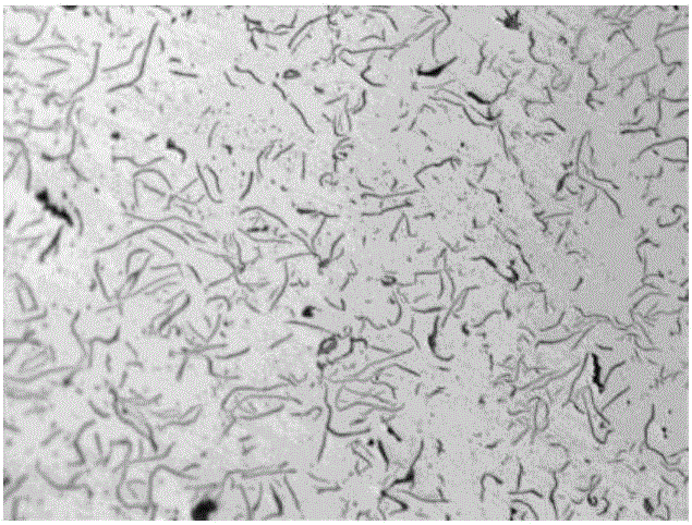
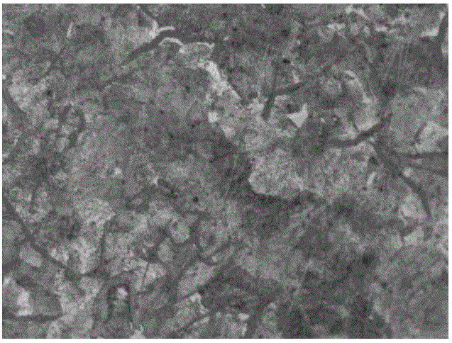
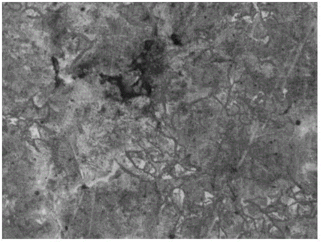
Image
Examples
Example Embodiment
[0040] The invention provides a method for preparing a high-strength cylinder liner, which includes the following steps:
[0041] a) The raw materials are smelted to obtain molten iron;
[0042] b) The inoculation of the molten iron to obtain the inoculated molten iron; the content of C in the inoculated molten iron is 2.8-3.4 wt%, the content of S is 0-0.1 wt%, and the content of Si is 1.5-2.5 wt%, the content of P is 0.1-0.4wt%, the content of Mn is 0.5-0.8wt%, the content of Cr is 0.1-0.4wt%, the content of Mo is 0.2-0.5wt%, the total content of Cu and Ni is 0.2~0.5wt%, Fe content is the balance;
[0043] c) Centrifugal casting of the inoculated molten iron to obtain a high-strength cylinder liner.
[0044] In the preparation method provided by the present invention, the raw materials are first smelted. Wherein, the temperature of the smelting is preferably 1480-1550°C, more preferably 1508-1510°C. After smelting is finished, molten iron is obtained.
[0045] After the iron liquid i
Example Embodiment
[0049] Example 1
[0050] (1) To smelt the raw materials, adjust the chemical composition of the molten iron, specifically: weigh the specified raw materials in proportion, smelt them in an intermediate frequency induction furnace at 1510°C, and adjust the seasoning according to the following weight requirements: carbon: 3.10wt%, sulfur: 0.05wt%, Silicon: 1.5wt%, phosphorus: 0.13wt%, manganese: 0.55wt%, chromium: 0.12wt%, copper: 0.05wt%, nickel: 0.40wt%, molybdenum: 0.45wt%, iron: the balance to obtain molten iron ;
[0051] (2) Liquid iron pretreatment, specifically: adding a silicon-zirconium inoculant (ElkemPreseed, particle size 3-10mm) with a mass of 0.06% of the molten iron and a calcium silicate inoculant (Elkem Preseed, with a particle size of 0.06%) to the molten iron. 3~10mm), keep warm, and get one inoculation iron liquid;
[0052] (3) Iron inoculation, specifically: one inoculation of molten iron for downstream inoculation, using silicon strontium zirconium inoculant (Elk
Example Embodiment
[0056] Example 2
[0057] (1) To smelt the raw materials, adjust the chemical composition of the molten iron, specifically: weigh the specified raw materials in proportion, smelt them in an intermediate frequency induction furnace at 1508°C, and perform the seasoning according to the following weight requirements: carbon: 3.04wt%, sulfur: 0.052wt%, Silicon: 1.6wt%, phosphorus: 0.12wt%, manganese: 0.53wt%, chromium: 0.13wt%, copper: 0.08wt%, nickel: 0.36wt%, molybdenum: 0.46wt%, iron: the balance to obtain molten iron ;
[0058] (2) Liquid iron pretreatment, specifically: adding a silicon-zirconium inoculant (ElkemPreseed, particle size 3-10mm) of 0.05% of the liquid iron mass and a calcium-silica inoculant (Elkem Preseed, particle size of 0.05%) to the liquid iron 3~10mm), keep warm, and get one inoculation iron liquid;
[0059] (3) Iron inoculation, specifically: one inoculation of molten iron for downstream inoculation, using silicon-strontium-zirconium inoculant (ElkemSuperseed Ext
PUM
| Property | Measurement | Unit |
|---|---|---|
| Granularity | aaaaa | aaaaa |
| Granularity | aaaaa | aaaaa |
| Tensile strength | aaaaa | aaaaa |
Abstract
Description
Claims
Application Information
 - R&D Engineer
- R&D Manager
- IP Professional
- Industry Leading Data Capabilities
- Powerful AI technology
- Patent DNA Extraction
Browse by: Latest US Patents, China's latest patents, Technical Efficacy Thesaurus, Application Domain, Technology Topic.
© 2024 PatSnap. All rights reserved.Legal|Privacy policy|Modern Slavery Act Transparency Statement|Sitemap


