Gas analyzer and gas analysis method

A gas analyzer and gas detection technology, applied in the direction of material analysis, material analysis through optical means, instruments, etc., can solve the problems that are not conducive to the miniaturization of instruments, inaccurate measurement, expensive cost, etc., to overcome moisture interference, measure accurate effect

Active Publication Date: 2017-11-24
HUBEI RUIYI AUTOMATIC CONTROL SYST CO LTD +1
View PDF9 Cites 7 Cited by
  • Summary
  • Abstract
  • Description
  • Claims
  • Application Information

AI Technical Summary

Problems solved by technology

For example, "Non-dispersive infrared (NDIR) dual tracegas analyzer and method for determining a concentration of a measurement gas component in a gas mixture by the gas analyzer" proposed by SIEMENS AKTIENGESELLSCHAFT in the patent document US20130043391A1: the gas chamber is a fork-shaped double-tube dual-gas The chamber structure is large, which is not conducive to the miniaturization of the instrument. The process structure is complicated and the cost is expensive; Gas interference; In addition, the infrared light source uses a beam splitter, which will cause signal loss due to infrared light reflection and inaccurate measurement
In the patent document EP0093939A1, the "Non-dispersive infrared gasanalyzer" proposed by FUJI ELECTRIC CO.LTD: the air chamber is a single

Method used


Image

  • Gas analyzer and gas analysis method
  • Gas analyzer and gas analysis method
  • Gas analyzer and gas analysis method

Examples


Embodiment 1

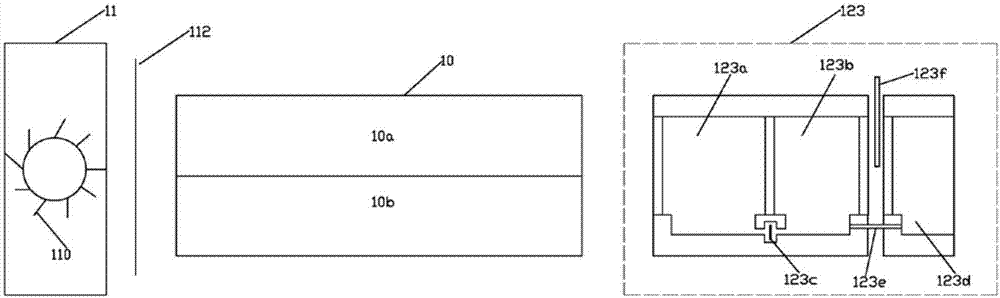
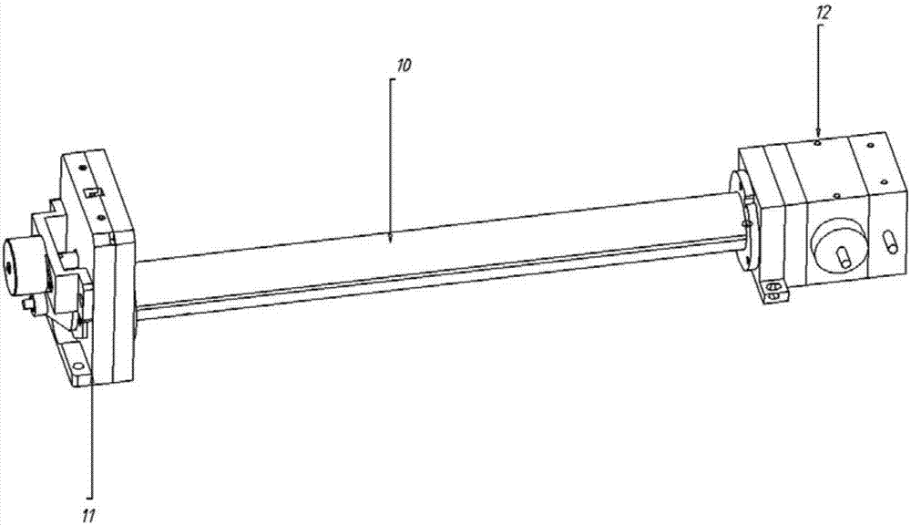
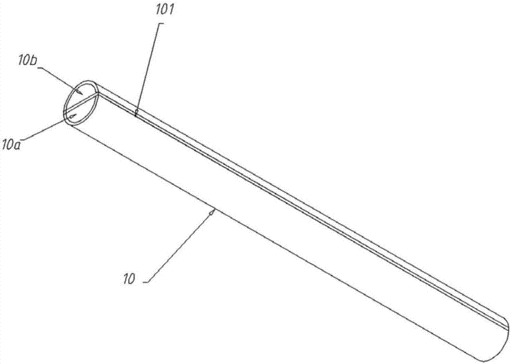
[0048] reference figure 1 —5. A gas analyzer, including a cavity 10, a light source module 11, a light receiving module 12, and a processing unit 13. One end of the cavity 10 is connected to the light source module 11, and the other end is connected to the light receiving module 12 through The partition 101 arranged at the central axis of the cavity 10 divides the cavity 10 into two air chambers of the same size and shape, namely the reference air chamber 10a and the measurement air chamber 10b. In this embodiment, the reference air chamber 10a The measuring gas chamber 10b is symmetrically arranged with respect to the partition 101, and the cross-sections of the reference gas chamber 10a and the measuring gas chamber 10b are both set to be semicircular. It should be considered that in actual applications, rectangular cross-sections or other geometric shapes are within the protection scope of this scheme.

[0049] The partition 101 has the same length as the cavity 10. The partitio

Embodiment 2

[0081] reference Figure 5-8 , A gas analysis method applied to the gas analyzer described in the first embodiment, including the following steps:

[0082] S1: Fill the measuring gas chamber 10b with a measured gas of a known concentration. In this embodiment, the measured gas is SO2 for example;

[0083] S2: Fill the reference gas chamber 10a with N2;

[0084] S3: The light source 110 periodically and alternately irradiates the reference gas cell 10a and the measurement gas cell 10b, the measured gas SO2 of known concentration absorbs the light emitted by the light source 110, and the reference gas N2 does not absorb the light emitted by the light source 110;

[0085] S4: The signals of the reference gas cell 10a and the measuring gas cell 10b are detected by the microfluidic infrared gas detection device 123, and the SO2 absorbed emission from the measuring gas cell 10b is received by the microfluidic infrared gas detection device 123 (for example, SO2 microfluidic infrared sensor) Th


PUM


Abstract

The invention provides a gas analyzer and a gas analysis method and belongs to the field of gas analysis. The gas analyzer has the advantages that a microflow half gas insulation chamber technology is adopted and measurement on to-be-detected gas is realized. The gas analyzer has main characteristics that one reference gas chamber and one measurement gas chamber are arranged in one cavity, and a microflow infrared gas detection device flowing front and back is adopted, so that the problems of large drift and poor measurement stability which are caused by adoption of a single gas chamber and the problem of complex structure due to adoption of an independent double-gas-chamber technology in the prior art are solved; besides, the microflow infrared gas detection device is provided with a water regulating device, and by finding the phenomenon that an absorption spectrum of vaporous water is overlaid with the absorption spectrum of the to-be-detected gas and utilizing difference in widths of absorption spectrums of the vaporous water and the to-be-detected gas on infrared lights, the water regulating valve is regulated, and variations of gases in front and rear gas chambers of the microflow infrared gas detection device and a water regulating buffer gas chamber after expansion are changed, so that a detected infrared spectrum is located in the absorption spectrum of the to-be-detected gas and is far away from the absorption spectrum of the vaporous water, and the problem of moisture disturbance is solved.

Description


Claims


Application Information

Patent Timeline
Owner HUBEI RUIYI AUTOMATIC CONTROL SYST CO LTD
Why Eureka
Try Eureka