Heating device special for aircraft oil tank

A technology of heating device and lubricating oil tank, applied in the aviation field, can solve problems such as fire hazards, achieve the effects of good manufacturability, ensure contact, and facilitate disassembly

Active Publication Date: 2019-01-11
SHAANXI AIRCRAFT CORPORATION
View PDF5 Cites 2 Cited by
  • Summary
  • Abstract
  • Description
  • Claims
  • Application Information

AI Technical Summary

Benefits of technology

This patented technology describes an improved way for heaters (which use Al) to keep them warm while working properly. It uses different materials like copper alloys, palladium resistor, thermocouple wires, and other components such as screws and nutings to make it easy to assemble into various shapes without damaging its properties during transportation. These devices help maintain their temperatures even when they get wet from rainwater overboard. Additionally, there're also features where these elements work together to create effective heat transmission systems. By combining this system with specific design options, users may have more flexibility than current designs.

Problems solved by technology

This patented technical problem addressed by this patents relates to improving safety during flight operations at very cold temperatures when an aircraft's engine needs it for longer periods without losing its performance or reliability due to insufficient coolant flow caused by poorly designed equipment like fuel pumps.

Method used


Image

  • Heating device special for aircraft oil tank
  • Heating device special for aircraft oil tank
  • Heating device special for aircraft oil tank

Examples


Embodiment Construction

[0017] A heating device of the present invention is described in detail in conjunction with the accompanying drawings:

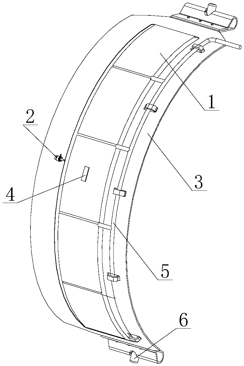
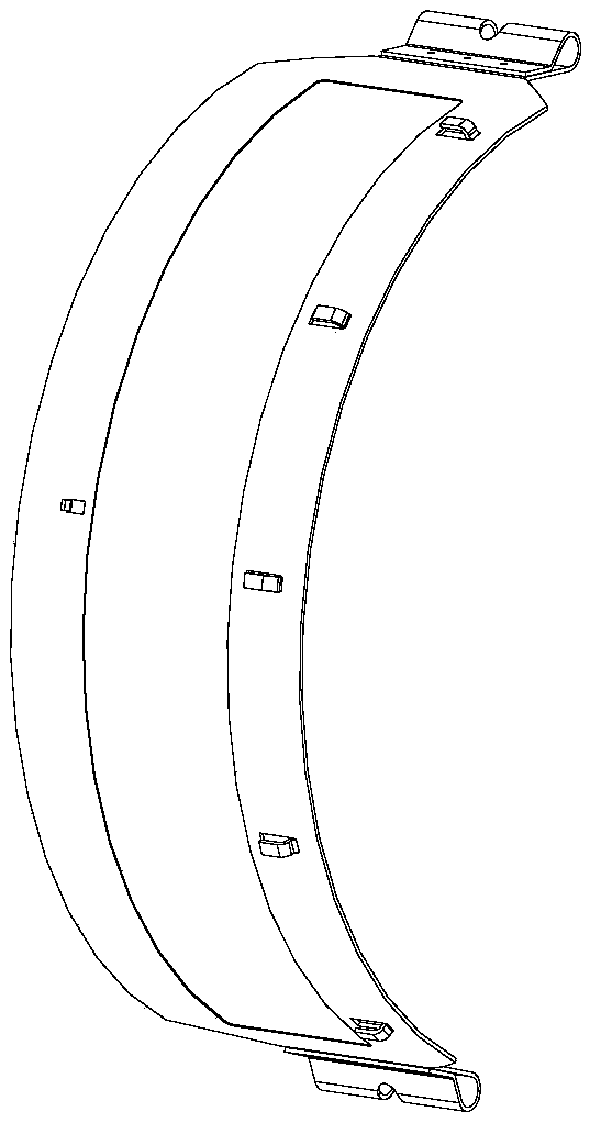
[0018] Such as figure 2 As shown, a heating device dedicated to an aircraft lubricating oil tank is provided, including a controller, a plurality of heating plates 1, a temperature relay 2, a housing part 3, a platinum resistor 4, a wire 5, and a sleeve 6.

[0019] In the heating device, the shell part 3 is an aluminum alloy material with good thermal conductivity; multiple heating plates 1 are evenly distributed on the shell part 3, and the shell part 3 is directly heated after being energized; the platinum resistor 4 is adhered to one of the heating plates 1, always detect the surface temperature of the heating plate 1, and convert the temperature signal into an electrical signal and transmit it to the controller; the temperature relay 2 is installed on the shell part 3, and when the platinum resistor 4 fails, it will replace it to monitor the temperature of


PUM


Abstract

The invention belongs to the technical field of aviation, and relates to a heating device special for an aircraft oil tank. Currently, most of existing heating devices are each of an insertion type structure, as aviation lubrication oil belongs to combustible liquid, the existing heating devices make direct contact with the lubrication oil, and fire risks are caused. The heating device isolates aheating assembly and the lubrication oil and then conducts heating through the thermal radiation principle. Heating is conducted on the outer side of the oil tank. The heating device comprises a controller and a shell component installed on the outer surface of the oil tank; a plurality of heating pieces are arranged on the outer surface of the shell component; the shell component is made of aluminum alloy materials; and a platinum resistor and a temperature relay can effectively ensure the effect that the heating device always keeps working within the safe temperature range. Efficient transferring of heat energy of the heating device is ensured, the heating device can be independently used or multiple heating devices are used at the same time according to the heating requirements, the structure is simple, dismounting is convenient, and interchangeability is good.

Description


Claims


Application Information

Patent Timeline
Owner SHAANXI AIRCRAFT CORPORATION
Why Eureka
Try Eureka