Microstrip waveguide converter for radar level meter

A waveguide converter and microstrip technology, applied in the microwave field, can solve the problems of difficult coaxial lines and small size, and achieve the effects of improving sensitivity and detection range, reducing assembly difficulty, and improving insertion loss and standing wave indicators.

Pending Publication Date: 2019-03-12
智驰华芯(无锡)传感科技有限公司 +1
View PDF0 Cites 4 Cited by
  • Summary
  • Abstract
  • Description
  • Claims
  • Application Information

AI Technical Summary

Problems solved by technology

In this structure, the signal needs to go through microstrip-coaxial and coaxial-waveguide conversion twice from the radio frequency circuit board to the horn antenna, which inevitably brings problems of insertion loss and return loss. For radar level gauges, Especially for radar level gauges working in FMCW (frequency modulated continuous wave) mode, the large insertion loss and poo

Method used


Image

  • Microstrip waveguide converter for radar level meter
  • Microstrip waveguide converter for radar level meter
  • Microstrip waveguide converter for radar level meter

Examples


Embodiment Construction

[0017] The specific embodiments of the present invention will be further described below in conjunction with the drawings.

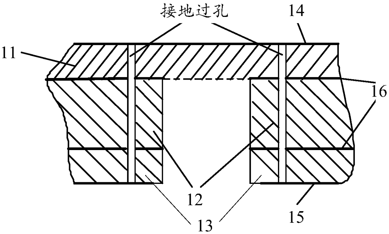
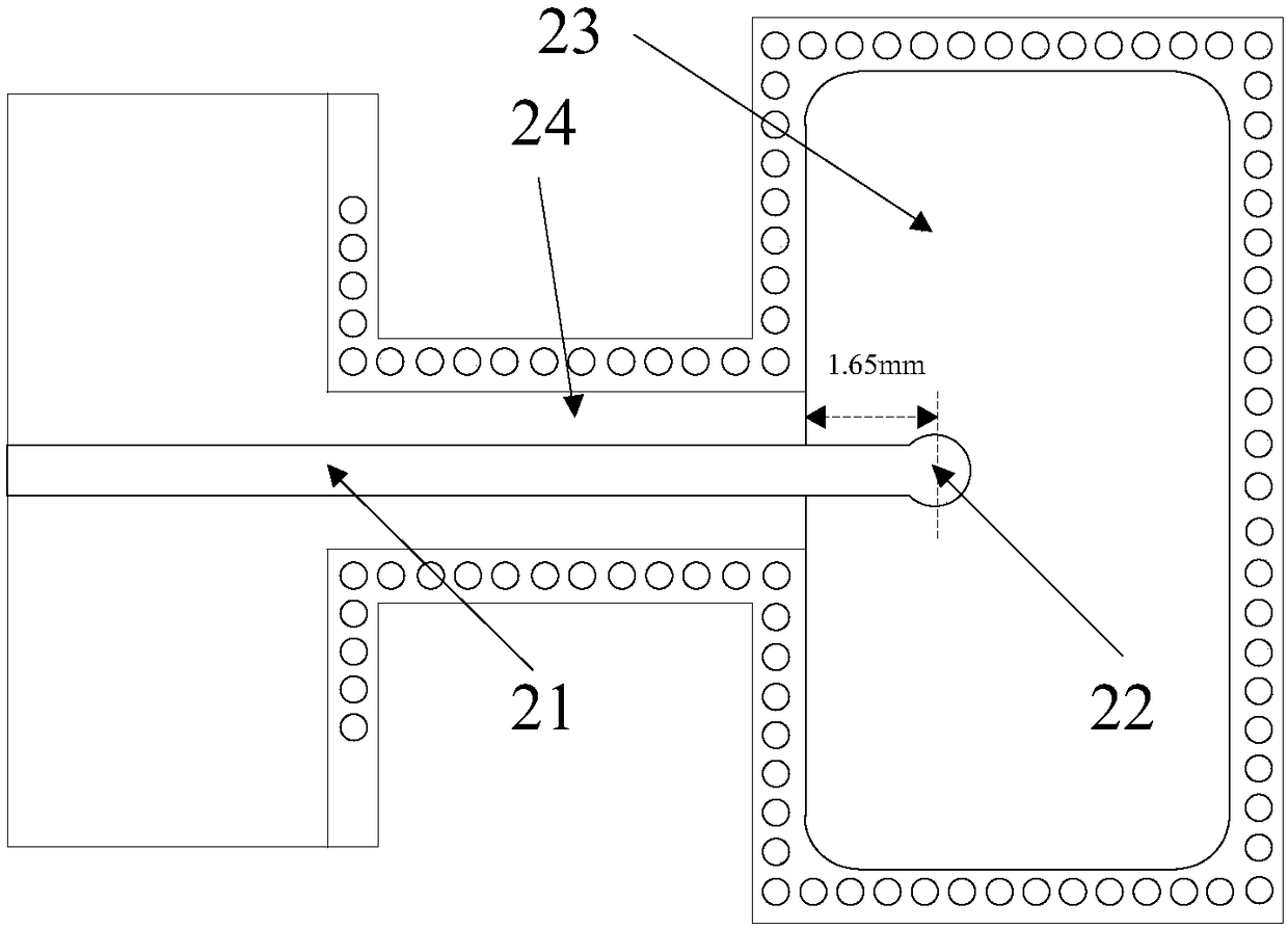
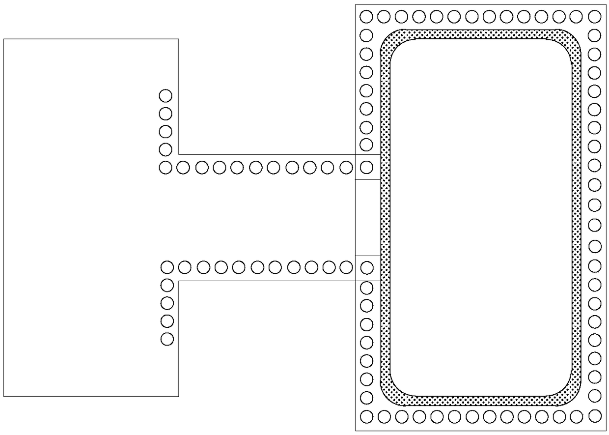
[0018] This application discloses a microstrip waveguide converter for a radar level meter. The microstrip waveguide converter is based on a multilayer mixed voltage circuit board, and the multilayer mixed voltage circuit board is provided with a microstrip line, a coupling probe and Ground vias, ground vias penetrate through the multilayer hybrid circuit board, and the microstrip line and coupling probes are located on the top metal layer of the multilayer hybrid circuit board. The rectangular waveguide is pressed tightly on the bottom metal layer of the multilayer mixed-voltage circuit board by screws, and the microstrip line extends from the middle of the wide side of the rectangular waveguide cavity into the rectangular waveguide cavity and transforms into a coupling probe to achieve coupling. It is located in the rectangular waveguide cavity Except for th


PUM

PropertyMeasurementUnit
Lengthaaaaaaaaaa
Widthaaaaaaaaaa
Thicknessaaaaaaaaaa

Abstract

The invention discloses a microstrip waveguide converter for a radar level meter, relating to the technical field of microwave. The converter can directly convert a microstrip signal into a waveguidesignal, and adopts a probe structure with an advantageous insertion loss to improve the insertion loss and standing wave index of the microwave signal from the PCB to the horn antenna transmission stage, thereby improving the sensitivity and detection range of the level meter. At the same time, the installation is realized all by screws, which reduces the assembly difficulty, eliminates the assembly of semi-steel coaxial cables in a narrow space, and improves the production efficiency.

Description


Claims


Application Information

Patent Timeline
Owner 智驰华芯(无锡)传感科技有限公司
Why Eureka
Try Eureka