Broadband high-gain circularly polarized microstrip antenna

A microstrip antenna and high-gain technology, which is applied to antenna grounding devices, antenna arrays that are powered independently, and antenna grounding switch structural connections, etc., can solve the problem of increasing antenna feed loss, increasing processing complexity, and increasing antenna size, etc. problem, to achieve the effect of wide axial ratio bandwidth, reduce lateral leakage, and reduce feed loss

Inactive Publication Date: 2019-05-03
BEIJING RES INST OF TELEMETRY +1
View PDF4 Cites 17 Cited by
  • Summary
  • Abstract
  • Description
  • Claims
  • Application Information

AI Technical Summary

Problems solved by technology

Common broadband circularly polarized microstrip antennas generally use double-layer (or multi-layer) multi-feed point excitation. The double-layer (or multi-layer) microstrip structure reduces the isolation of th

Method used


Image

  • Broadband high-gain circularly polarized microstrip antenna
  • Broadband high-gain circularly polarized microstrip antenna
  • Broadband high-gain circularly polarized microstrip antenna

Examples


Embodiment Construction

[0027] The present invention will be further described below in conjunction with accompanying drawing.

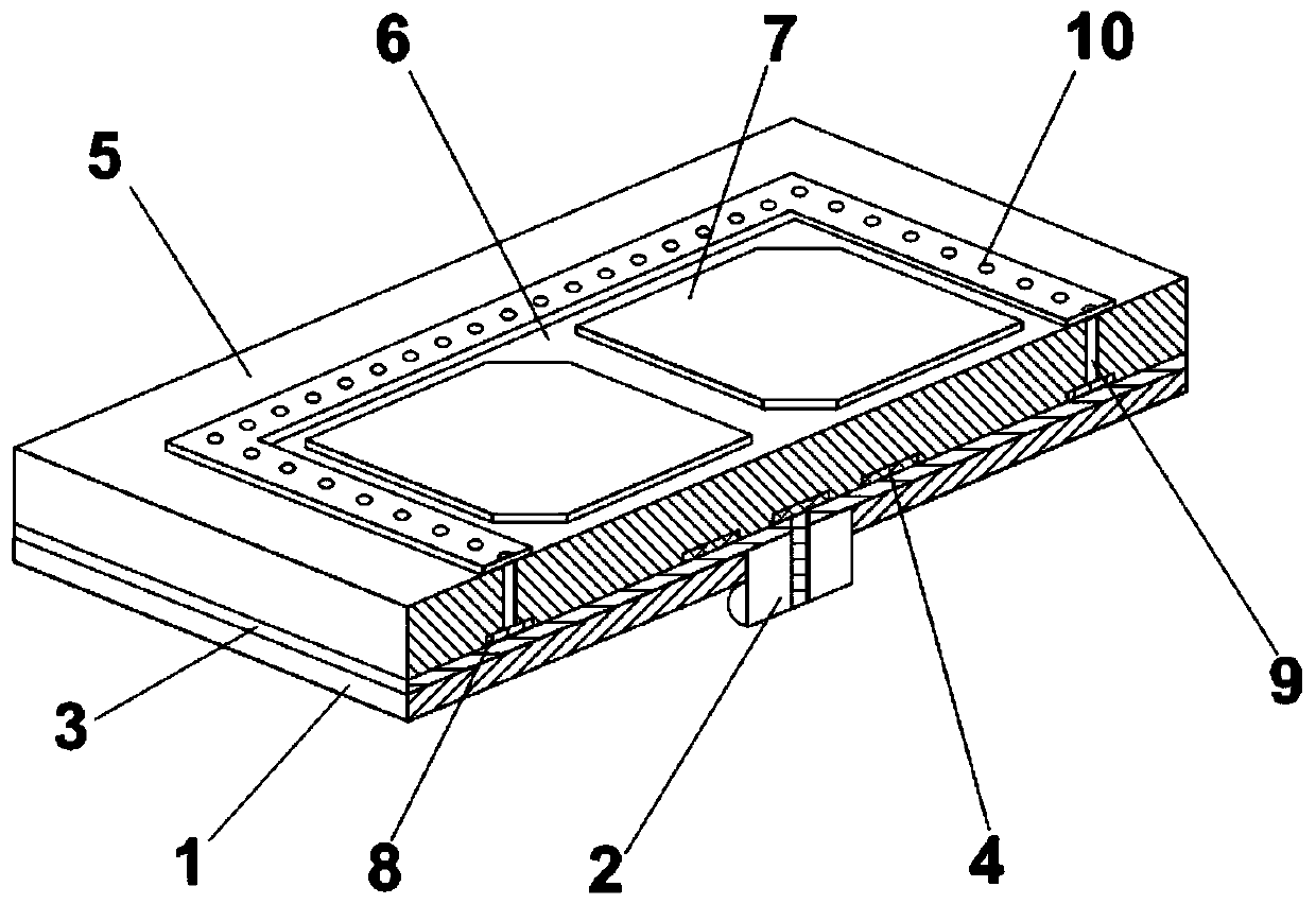
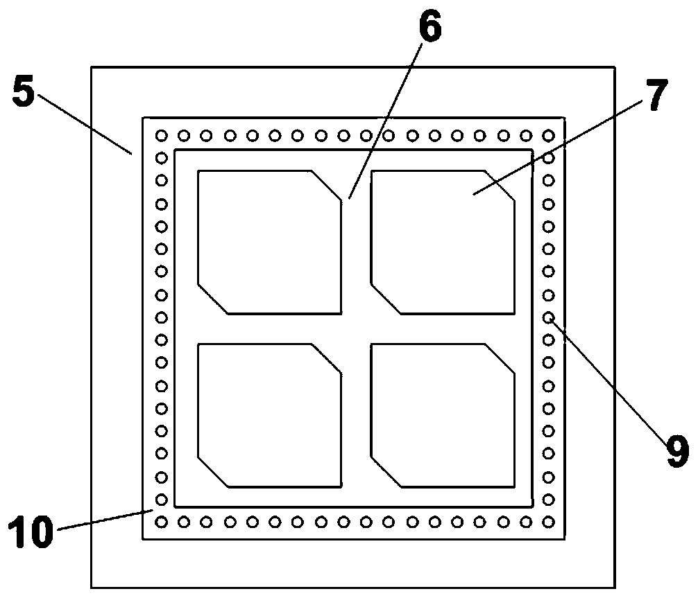
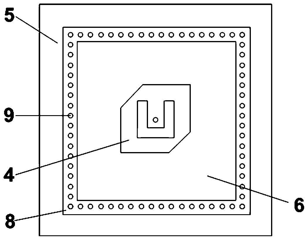
[0028] figure 1 Shown is the schematic diagram of the layered structure of the antenna of the present invention, as can be seen from the figure, the wide-band high-gain circularly polarized microstrip antenna proposed by the present invention includes: floor 1, feed coaxial 2, bottom dielectric substrate 3, cut corner U-shaped groove microstrip 4, top layer dielectric substrate 5, substrate integrated waveguide square cavity 6, microstrip radiation unit 7; the microstrip antenna of the present invention can be processed by common double-layer microstrip printed board technology, and can also be processed by LTCC Craft realized.

[0029] Among them, the structural floor (1) is located at the bottom of the antenna and is made of metal, the bottom dielectric substrate 3 is located on the upper layer of the floor 1 and is in close contact, the top dielectric substrate 5 is locate


PUM


Abstract

A broadband high-gain circularly polarized microstrip antenna comprises a floor, a feed coaxial, a bottom dielectric substrate, a chamfered U-shaped slot microstrip, a top dielectric substrate, a substrate integrated waveguide square cavity, and a 2*2 microstrip radiation unit. The substrate integrated waveguide square cavity is composed of a bottom square microstrip line, a metal cylinder array,a top square microstrip line, and a part of the top dielectric substrate surrounded by the metal cylinder array. The respective parts of the antenna are stacked in order from bottom to top. The antenna can be achieved by a common double-layer microstrip printed board process or by an LTCC process. The method uses a form that a single-point feeding lower microstrip excites the upper 2*2 microstripradiation unit through the substrate integrated waveguide square cavity, increases the gain while realizing a wide frequency band, thereby avoiding the use of a complicated feed network. The circularpolarization of the antenna is achieved by means of chamfering on two rectangular microstrips. The antenna can be used as a single antenna or as a wide-angle scanning array antenna element.

Description


Claims


Application Information

Patent Timeline
Owner BEIJING RES INST OF TELEMETRY
Why Eureka
Try Eureka