Vibration measuring device and method based on millimeter waves

A technology of vibration measurement and millimeter wave, applied in the direction of measuring devices, measuring ultrasonic/sonic/infrasonic waves, using wave/particle radiation, etc., can solve the problems of high production cost, inconvenient application, and increase the cost of measuring devices, so as to achieve the goal of reducing costs Effect

Inactive Publication Date: 2019-06-14
SHENMU ZHANGJIAMAO COAL MINING CO LTD OF SHAANXI COAL & CHEM IND GRP
View PDF10 Cites 1 Cited by
  • Summary
  • Abstract
  • Description
  • Claims
  • Application Information

AI Technical Summary

Problems solved by technology

This method greatly limits the measurement scenarios and is very inconvenient to apply
[0005] To sum up, it can be seen that in the above methods, at least two collection nodes need to be set up to col

Method used


Image

  • Vibration measuring device and method based on millimeter waves
  • Vibration measuring device and method based on millimeter waves
  • Vibration measuring device and method based on millimeter waves

Examples


Embodiment Construction

[0041] The present invention will be described in detail below with reference to the drawings and specific embodiments.

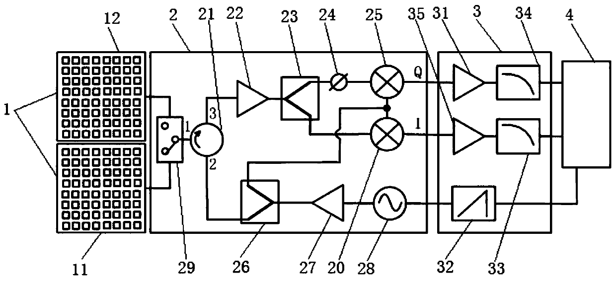
[0042] The invention discloses a vibration measurement device based on millimeter waves, such as figure 1 As shown, it includes an antenna array unit 1 for transmitting and receiving microwave beams. The antenna array unit 1 includes a transmitting antenna array 11 and a receiving antenna array 12. Each antenna in the antenna array unit 1 is provided with a shifter to control the beam Transmission and reception.

[0043] The antenna array unit 1 is connected to the data acquisition and processing unit 4 through the millimeter wave transceiver unit 2 and the baseband signal processing unit 3 in turn.

[0044] The millimeter wave transceiver unit 2 is used to generate millimeter wave signals and process the signals and transmit them to the antenna array unit 1. It is also used to process the millimeter wave signals received by the antenna array unit 1 to generate the q


PUM


Abstract

The invention discloses a vibration measuring device and method based on millimeter waves. The vibration measuring device includes an antenna array unit used for emitting and receiving microwave beams, wherein the antenna array unit is connected to a data acquiring and processing unit through a millimeter wave receiving and emitting unit and a baseband signal processing unit in sequence; and a millimeter wave signal is generated by the millimeter wave receiving and emitting unit and is emitted by the antenna array unit, an echo signal is further received through the antenna array unit, and a vibration state of a to-be-measured fan is calculated by the data acquiring and processing unit according to the echo signal. According to the vibration measuring device and method based on the millimeter waves, a millimeter wave array is used for constructing a beam in the specific direction, the direction of the beam is changed, different testing points can be tested at the same time, only one sampling point is needed to realize vibration measuring of the fan, and the whole measuring system cost is lowered.

Description


Claims


Application Information

Patent Timeline
Owner SHENMU ZHANGJIAMAO COAL MINING CO LTD OF SHAANXI COAL & CHEM IND GRP
Why Eureka
Try Eureka