Duplexer
A duplexer and resonator technology, applied in the field of semiconductors and micro-electromechanical systems, can solve the problems of difficult to guarantee the performance of the resonator, limit the overall performance of the filter, limited adjustable range, etc. Effects of out-of-band rejection and isolation improvement, improved in-band insertion loss and return performance
- Summary
- Abstract
- Description
- Claims
- Application Information
AI Technical Summary
Problems solved by technology
Method used
Image

Examples
Embodiment 1
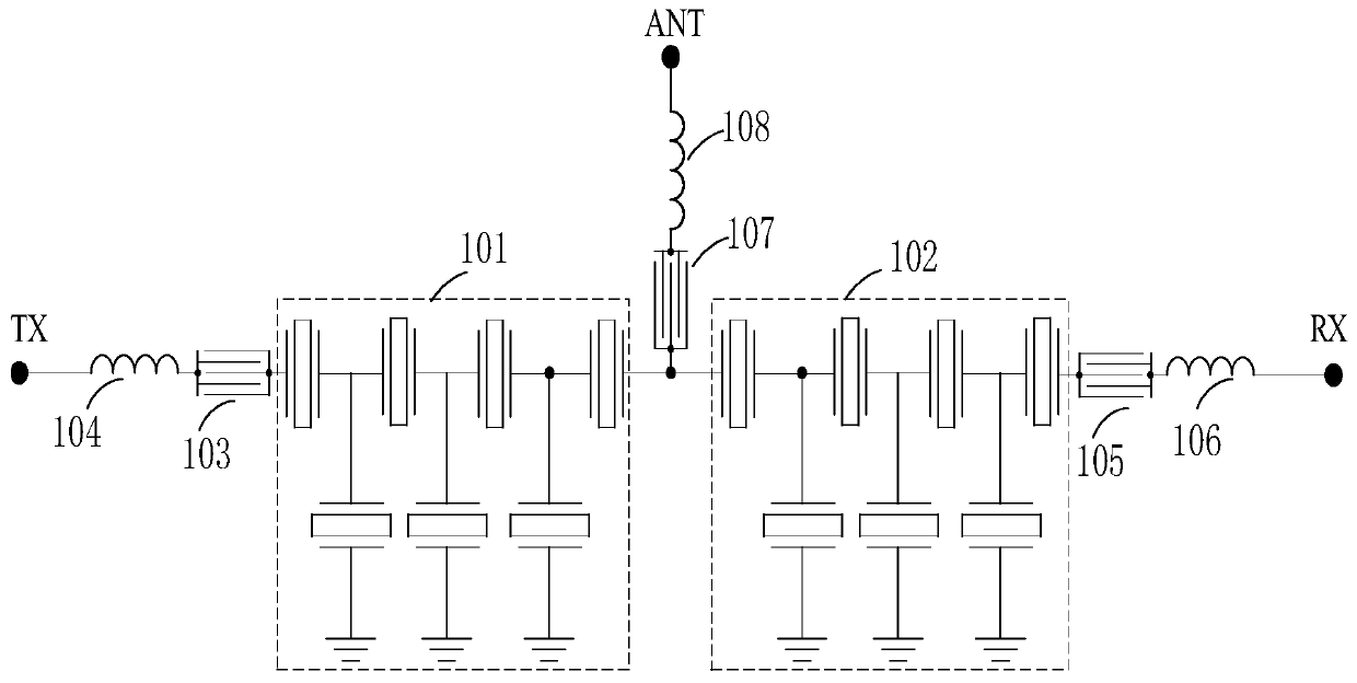
[0058] figure 1 A circuit structure diagram of the duplexer according to the first embodiment of the present application is shown. Such as figure 1 As shown, a duplexer includes:
[0059] a transmit filter 101 connected between a transmit terminal (TX) and an antenna terminal (ANT) and including series resonators and parallel resonators connected in a trapezoidal form; and
[0060] a receiving filter 102 connected between a receiving terminal (RX) and the antenna terminal (ANT) and comprising series resonators and parallel resonators connected in a trapezoidal form,
[0061] Among them, there are three groups of LWR resonators, one group of LWR resonators 103 and parasitic inductance 104 are connected in series between the transmitting filter 101 and the transmitting end (TX), and one group of LWR resonators 105 and parasitic inductance 106 are connected in series in receiving filter 102 Between the receiving end (RX), a group of LWR resonators 107 and parasitic inductance 108
Embodiment 2
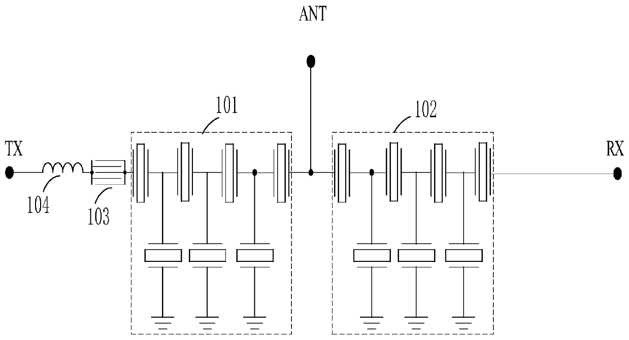
[0079] Figure 5 A circuit structure diagram of a duplexer according to the second embodiment of the present application is shown. Such as Figure 5 As shown, a duplexer includes:
[0080] a transmit filter 101 connected between a transmit terminal (TX) and an antenna terminal (ANT) and including series resonators and parallel resonators connected in a trapezoidal form; and
[0081] a receiving filter 102 connected between a receiving terminal (RX) and the antenna terminal (ANT) and comprising series resonators and parallel resonators connected in a trapezoidal form,
[0082] Wherein, there are two groups of LWR resonators, one group of LWR resonators 109 and parasitic inductance 110 are connected in series between the parallel resonators near the antenna end (ANT) of the transmitting filter 101 and the ground terminal, and the other group of LWR resonators 111 and The parasitic inductance 112 is connected in series between the parallel resonator near the antenna end (ANT) of
Embodiment 3
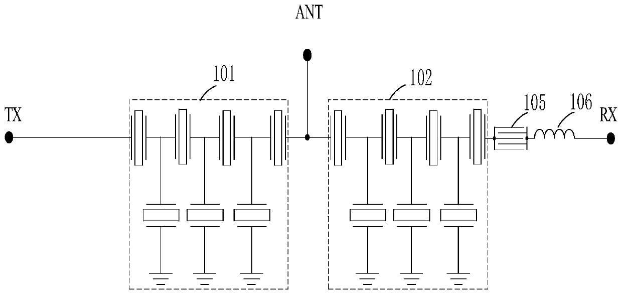
[0095] Figure 8 A circuit structure diagram of a duplexer according to the third embodiment of the present application is shown. Such as Figure 8 As shown, a duplexer includes:
[0096] a transmit filter 101 connected between a transmit terminal (TX) and an antenna terminal (ANT) and including series resonators and parallel resonators connected in a trapezoidal form; and
[0097] a receiving filter 102 connected between a receiving terminal (RX) and the antenna terminal (ANT) and comprising series resonators and parallel resonators connected in a trapezoidal form,
[0098] Wherein, the LWR resonators are two groups, one group of LWR resonators 113 and the parasitic inductance 114 are connected in series on the parallel road drawn by the parallel resonators near the antenna end (ANT) of the transmitting filter 101, and the other group of LWR resonators 115 and the parasitic inductance The inductance 116 is connected in series on the parallel path drawn from the parallel reson
PUM
 Abstract
Description
Claims
Application Information
 - R&D Engineer
- R&D Manager
- IP Professional
- Industry Leading Data Capabilities
- Powerful AI technology
- Patent DNA Extraction
Browse by: Latest US Patents, China's latest patents, Technical Efficacy Thesaurus, Application Domain, Technology Topic.
© 2024 PatSnap. All rights reserved.Legal|Privacy policy|Modern Slavery Act Transparency Statement|Sitemap