Flue gas white smoke removal equipment for intelligent production factory of rubber plant

A technology for intelligent production and rubber factories, applied in lighting and heating equipment, cleaning methods and utensils, cleaning hollow objects, etc., can solve problems such as doping and lowering of flue gas quality

Active Publication Date: 2019-12-03
山东保蓝环保有限公司
View PDF10 Cites 5 Cited by
  • Summary
  • Abstract
  • Description
  • Claims
  • Application Information

AI Technical Summary

Benefits of technology

This invention describes an apparatus for removing impurities from pipelines or other equipment by circulation-based methods that involve flowing them into specific areas where they can be collected with help of special tools like scrapers or brushes. These techniques are effective at clearing blockages caused during operation without causing damage to the pipeline itself.

Problems solved by technology

This technical issue addressed in this patented text relates to improving the efficiency of removing sulfur from combustion gases used in industrial processes such as power generation or chemical manufacturing operations. Current methods involve condensation onto surfaces inside the furnace where they are emitted during operation due to high temperatures caused by heat transfer between different parts within the device's structure. Additionally, these devices may also accumulate harmful substances on their interior walls overtime causing them to become colored like muddy swirl along its length. These issues make cleanup difficult without damaging sensitive components located near critical areas.

Method used


Image

  • Flue gas white smoke removal equipment for intelligent production factory of rubber plant
  • Flue gas white smoke removal equipment for intelligent production factory of rubber plant

Examples


Embodiment Construction

[0020] The following will clearly and completely describe the technical solutions in the embodiments of the present invention with reference to the accompanying drawings in the embodiments of the present invention. Obviously, the described embodiments are only some, not all, embodiments of the present invention. Based on the technical solutions in the present invention, all other embodiments obtained by persons of ordinary skill in the art without making creative efforts belong to the protection scope of the present invention.

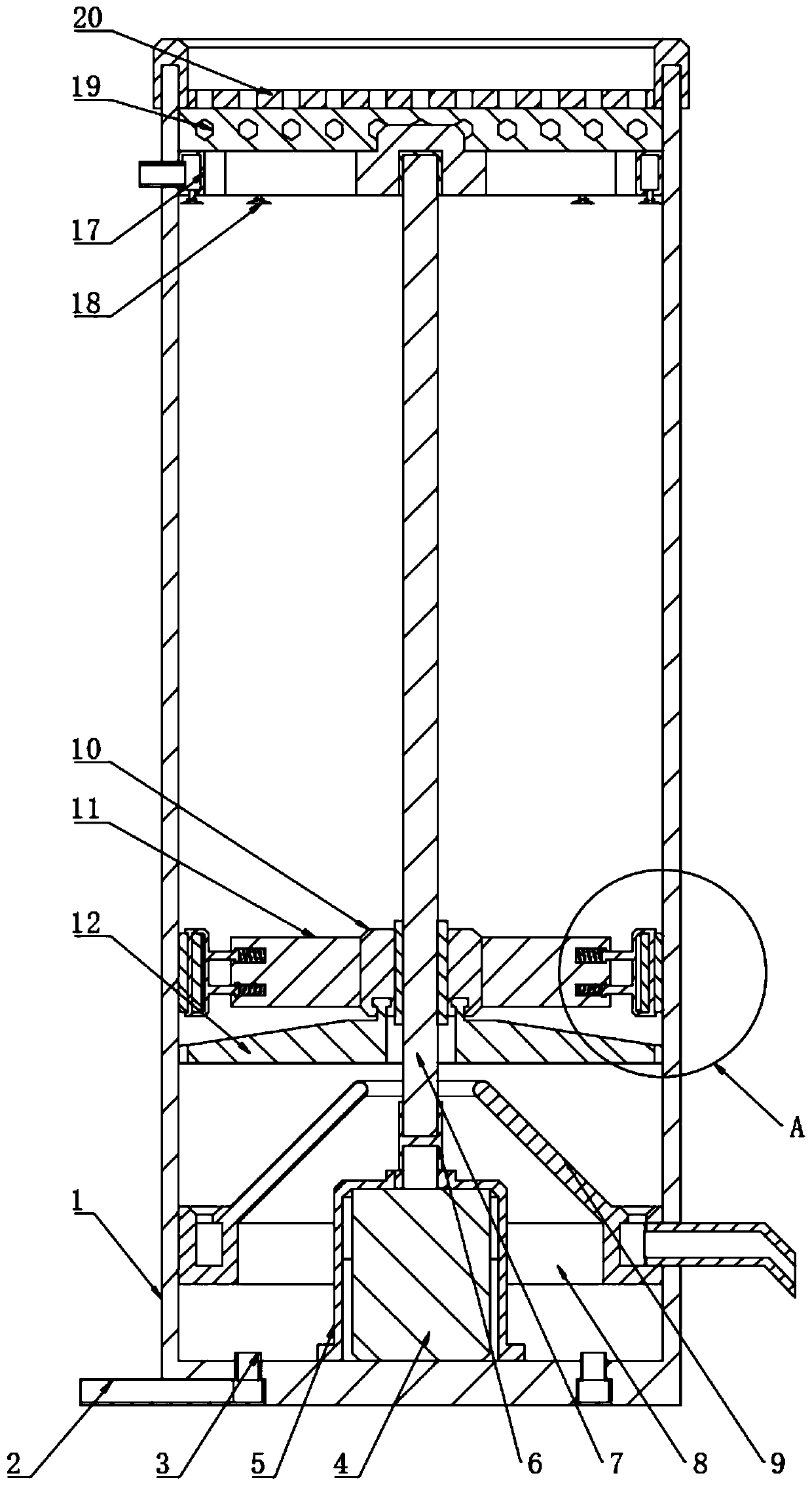
[0021] see Figure 1 to Figure 2 , the present invention provides a technical solution: a flue gas de-whitening equipment for intelligent production plants in rubber factories, including a chimney tube 1, and an inlet ring 2 is arranged at the bottom of the chimney tube 1, and the inlet ring 2 is equally spaced and evenly spaced. Several sets of intake pipes 3 are welded, the intake ring 2 is a hollow ring inserted at the bottom of the chimney tube 1, and


PUM


Abstract

The invention relates to the field of environmental protection equipment, specifically relates to flue gas white smoke removal equipment for an intelligent production factory of a rubber plant. The equipment has a chimney tube; an air inlet ring is inserted into the bottom of the chimney tube; a plurality of groups of air inlet pipes are uniformly welded on the air inlet ring at equal intervals; adriving motor is arranged in the center of the bottom of the chimney tube; a dustproof sleeve is arranged outside the driving motor in a sleeving manner; a connecting shaft sleeve sleeves a rotatingshaft at the top of the driving motor; a threaded rod is inserted into the top of the connecting shaft sleeve, a waste liquid ring is attached to the bottom of the inner wall face of the chimney tube,a collecting funnel is welded to the edge of the inner side of the upper surface of the waste liquid ring, the threaded rod is sleeved with a rotating sleeve, and four sets of cleaning blades are evenly welded to the side face of the rotating sleeve at equal intervals in a surrounding mode. According to the equipment, cleaning rollers are attached to the inner wall face of the chimney tube to roll through elastic force of compression springs, and sundries attached to the inner wall face of the chimney tube are cleaned through rotation of the cleaning rollers.

Description


Claims


Application Information

Patent Timeline
Owner 山东保蓝环保有限公司
Why Eureka
Try Eureka