Hydro-power generation type competitive spinning system
A technology for spinning and cycling, applied in engine components, machines/engines, training equipment for regulating cardiovascular system, etc., can solve problems such as affecting the power and confidence of exercisers, environmental pollution, and low energy storage efficiency of batteries
- Summary
- Abstract
- Description
- Claims
- Application Information
AI Technical Summary
Problems solved by technology
Method used
Image


Examples
Embodiment 1
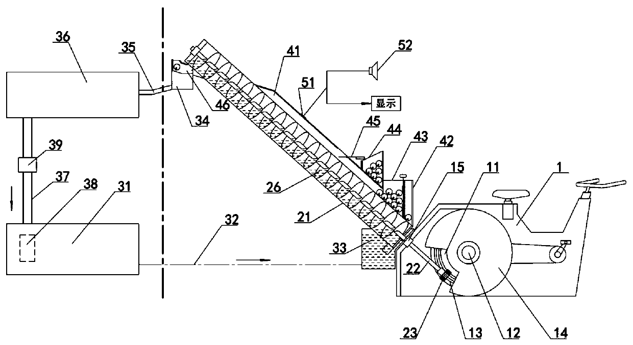
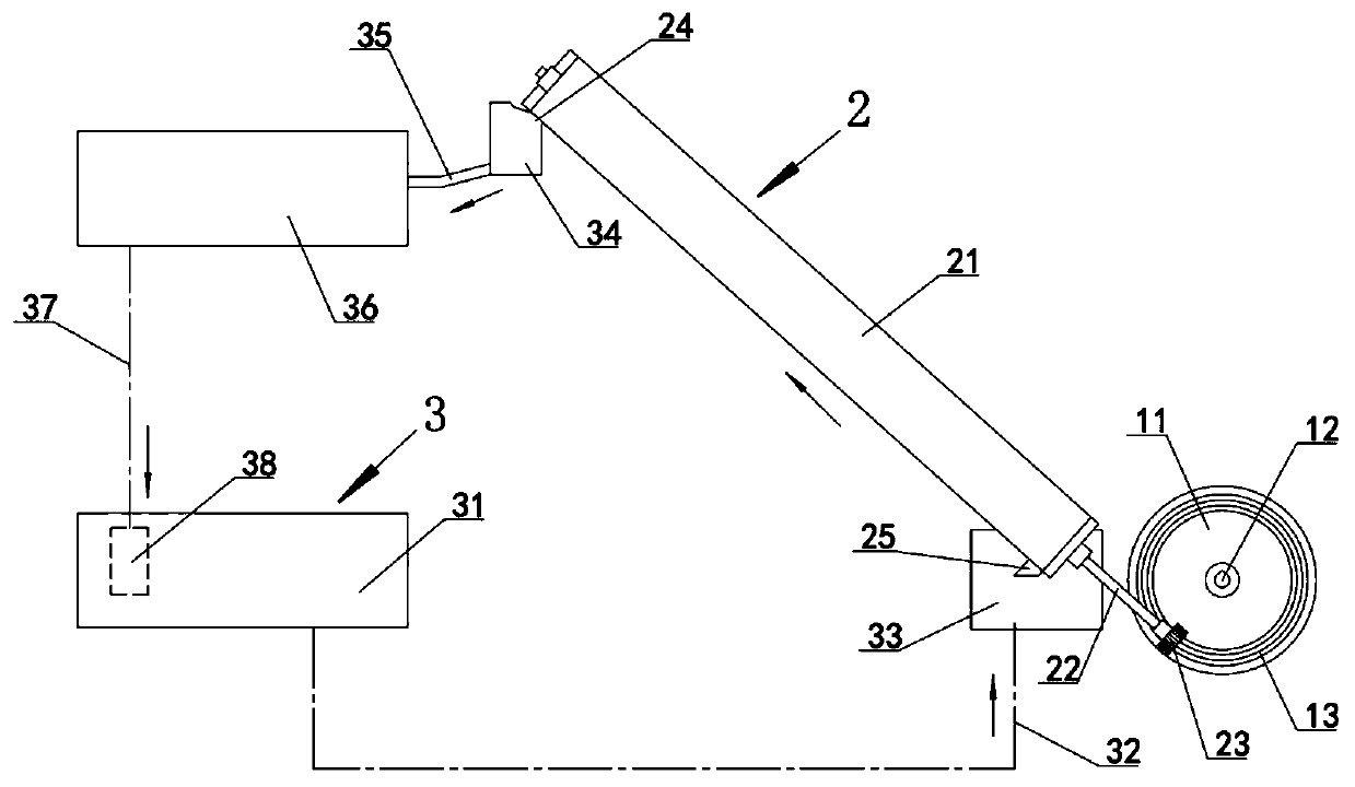
[0025] Embodiment 1: as figure 1The competitive spinning system shown is to lift the lower water tank 31 to the upper water tank 36 through the screw lifting mechanism 2, and then can also use the height difference between the upper and lower water tanks to realize the application of hydropower generation. In the process of lifting the lower water tank 31 to the upper water tank 36 by the screw lifting mechanism 2, at the same time, drop a float at the bottom of the screw lifting mechanism 2, usually a marked float, such as a special mark or name or avatar for a certain competitive athlete The floating ball is driven upward by the screw lifting mechanism 2 along with the water flow. In the process of realizing the movement of the screw lifting mechanism 2, it is a laborious process. The screw lifting mechanism 2 is driven by the bicycle mechanism to work. Competitors determine the outcome by comparing the movement speed and movement time. It is very suitable for longitudinal move
Embodiment 2
[0044] Embodiment 2: On the basis of Embodiment 1, based on the above design, the fully automatic circulation mode of the floating ball can be realized while lifting the water, which can be applied to general fitness personnel and can achieve a targeted competition mode, which is suitable for competitions in public places and entertainment. In order to improve the flexibility of switching between the two, you can choose to use such as Figure 4 with Figure 5 The reversing mechanism 45 shown. As can be seen from the figure, a reversing mechanism 45 is provided on the upper side wall of the ball return channel 41 at the upper part of the manual ball storage chamber 44, and the reversing mechanism 45 includes a lead-out hole 454 provided on the upper side wall of the ball return channel 41. The lower edge of the export hole 454 is provided with a shaft hole and a pin shaft 452 is installed. A swing rod 451 is hinged on the pin shaft 452. One end of the swing rod 451 extends into
Embodiment 3
[0045] Embodiment 3: On the basis of Embodiment 1 or 2, there is an electronic counting and display mechanism, such as figure 1 with Figure 8 As shown, the mechanism includes a ball passing sensor 51 and a loudspeaker 52 installed on the sidewall of the ball return channel 41 , the passing ball sensor 51 transmits an induction signal to the controller and is released by the controller through the loudspeaker 52 . Simultaneously, the counter of the ball sensor 51 is also set, and the controller saves the data of the counter in the storage unit and puts it on the display.
PUM
 Abstract
Description
Claims
Application Information
 - R&D Engineer
- R&D Manager
- IP Professional
- Industry Leading Data Capabilities
- Powerful AI technology
- Patent DNA Extraction
Browse by: Latest US Patents, China's latest patents, Technical Efficacy Thesaurus, Application Domain, Technology Topic.
© 2024 PatSnap. All rights reserved.Legal|Privacy policy|Modern Slavery Act Transparency Statement|Sitemap