Metal plate forming mold and forming method thereof
A technology for sheet metal and forming molds, applied in forming tools, metal processing equipment, manufacturing tools, etc., can solve problems such as inability to fold metal sheets
- Summary
- Abstract
- Description
- Claims
- Application Information
AI Technical Summary
Problems solved by technology
Method used
Image

Examples
specific Embodiment approach 1
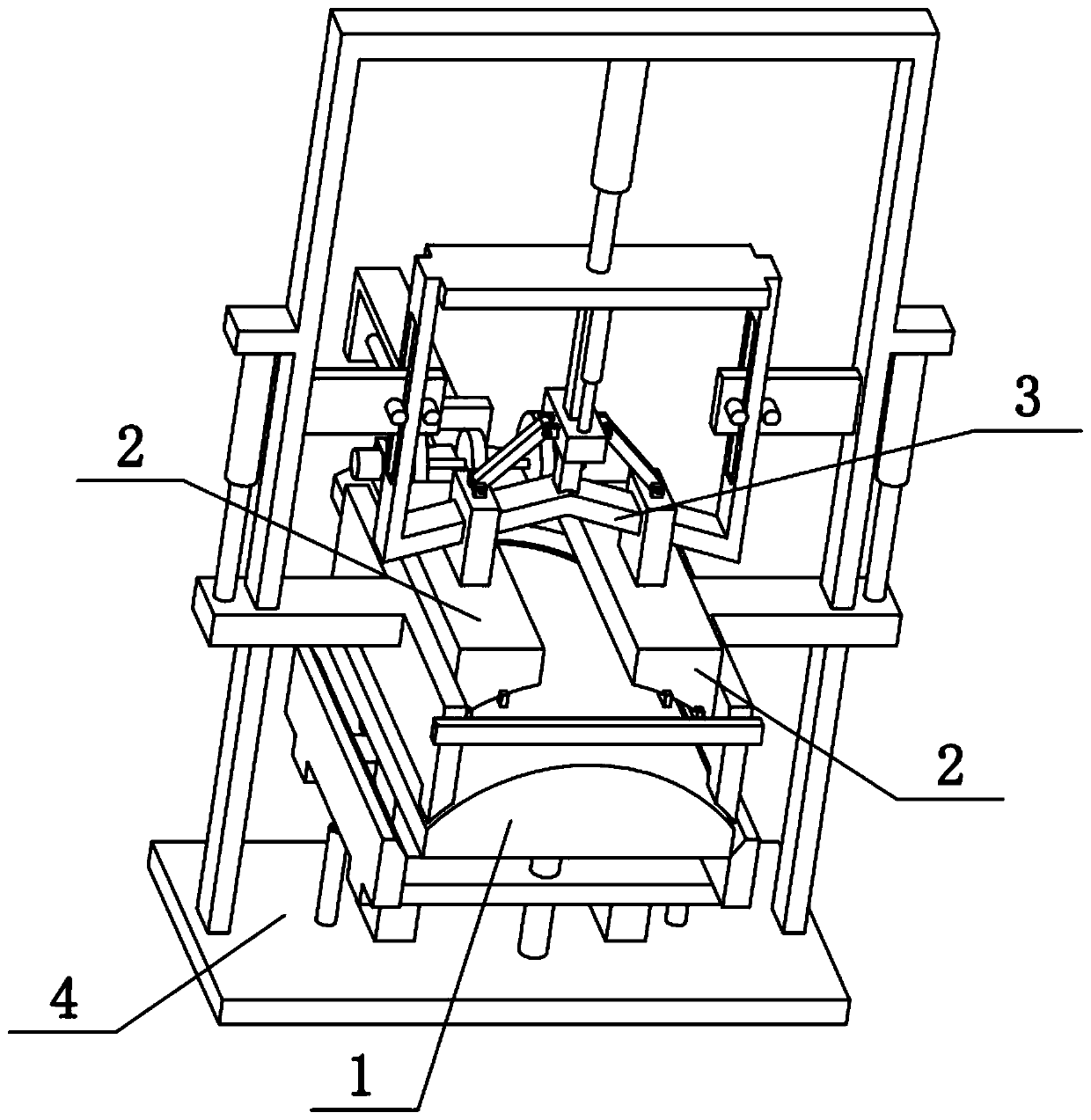
[0035] Combine below Figure 1-10 To illustrate this embodiment, the present invention relates to a mold, more specifically a sheet metal forming mold, which includes a convex seat 1, a side baffle 101, a bottom groove 103, a support column 104, a circular guide column 105, and a lifting bar 402 and hemming strip 403, the present invention can hem the metal plate.
[0036]The upper side of the convex seat 1 is a convex arc, the left and right sides of the convex seat 1 are provided with side baffles 101, the bottoms of the two side baffles 101 are all provided with bottom grooves 103, and the convex seat The left and right ends of the lower side of 1 are fixedly connected with supporting columns 104, the front and rear ends of the lower side of convex seat 1 are fixedly connected with round guide columns 105, and there are two hemming strips 403 on the left and right, two hemming strips 403 They are connected by two lifting bars 402, and the two lifting bars 402 are vertically s
specific Embodiment approach 2
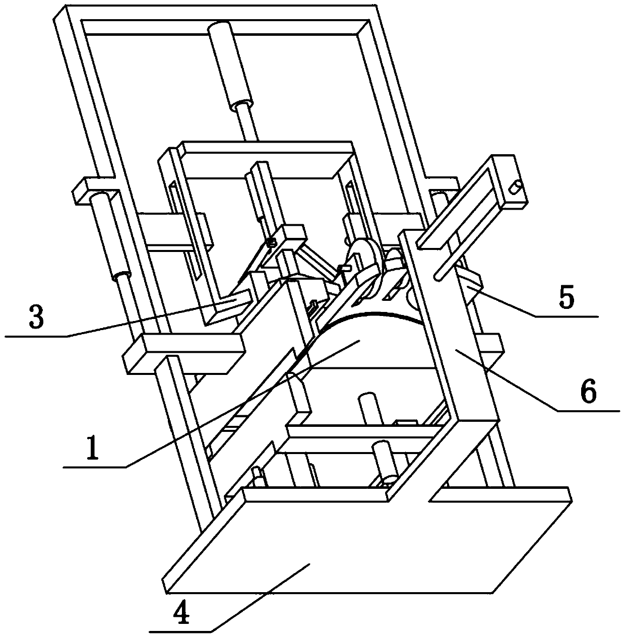
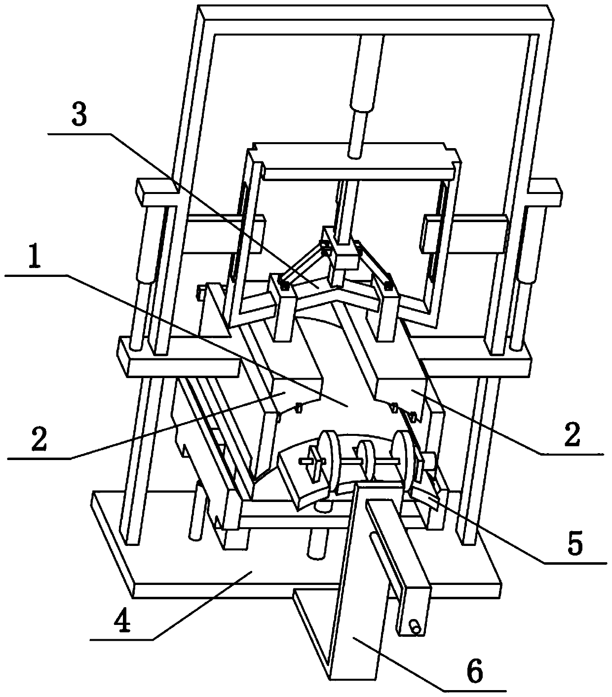
[0038] Combine below Figure 1-10 To illustrate this embodiment, the sheet metal forming die also includes a bottom plate 4 and an electric push rod II401, and the two support columns 104 are fixedly connected to the upper side of the bottom plate 4, and two electric push rods II401 are fixedly connected to the bottom plate 4. The upper ends of the two electric push rods II401 are respectively fixedly connected to the lower sides of the two hemming strips 403. When the two electric push rods II401 expand and contract at the same time, the two hemming strips 403 can be driven to lift simultaneously. At this time, the two lifting strips 402 move vertically on the two circular guide columns 105 respectively.
specific Embodiment approach 3
[0040] Combine below Figure 1-10 To illustrate this embodiment, the sheet metal forming die also includes a side convex plate 102, a horizontal connecting rod 106, a vertical frame rod 404 and an electric push rod III405, the left and right sides of the bottom plate 4 are fixedly connected with vertical frame rods 404, two The outer sides of the side baffles 101 are fixedly connected with side protruding plates 102, and the two side protruding plates 102 are respectively vertically slidably connected to the two vertical frame rods 404. Connection, the electric push rods III405 are fixedly connected to the two vertical rods 404, and the telescopic ends of the two electric push rods III405 are respectively fixedly connected to the two side convex plates 102. The two side baffles 101 are movable. When the metal sheet is folded, the two side baffles 101 are respectively pressed on the left and right ends of the convex seat 1. After the metal sheet is folded, the metal sheet needs to
PUM
 Abstract
Description
Claims
Application Information
 - R&D Engineer
- R&D Manager
- IP Professional
- Industry Leading Data Capabilities
- Powerful AI technology
- Patent DNA Extraction
Browse by: Latest US Patents, China's latest patents, Technical Efficacy Thesaurus, Application Domain, Technology Topic.
© 2024 PatSnap. All rights reserved.Legal|Privacy policy|Modern Slavery Act Transparency Statement|Sitemap