Anti-shrinkage resin sand mold riser device

A technology of resin sand and anti-shrinkage cavity, applied in casting and molding equipment, molds, cores, etc., can solve the problems of increasing labor intensity of workers, large-area holes in profiles, and difficulty in grinding and cleaning of risers. Pouring efficiency, preventing shrinkage and shrinkage defects, and beneficial to the effect of liquid replenishment

Pending Publication Date: 2020-12-11
沪航科技集团有限公司
View PDF0 Cites 0 Cited by
  • Summary
  • Abstract
  • Description
  • Claims
  • Application Information

AI Technical Summary

Problems solved by technology

[0003] At present, when casting resin sand, it is often necessary to use a riser to feed the casting to prevent defects to a certain extent. However, in the actual production process, cutting the riser requires a lot of energy consumption, and it is difficult to grind and clean the riser. , increasing the labor intensity of the staff
At the same time, during the pouring process, due to poor exhaust or external air entering the mold cavity through the riser, the cavity is burned and gasified at high temperature, and the gas is involved to cause choking, resulting in large-area holes and irregularities in the profile. Trachoma, resulting in low pass rate of castings

Method used


Image

  • Anti-shrinkage resin sand mold riser device
  • Anti-shrinkage resin sand mold riser device
  • Anti-shrinkage resin sand mold riser device

Examples


Example Embodiment

[0013] The present invention will be further described in conjunction with the accompanying drawings and specific embodiments.

[0014] Embodiments of the invention are:

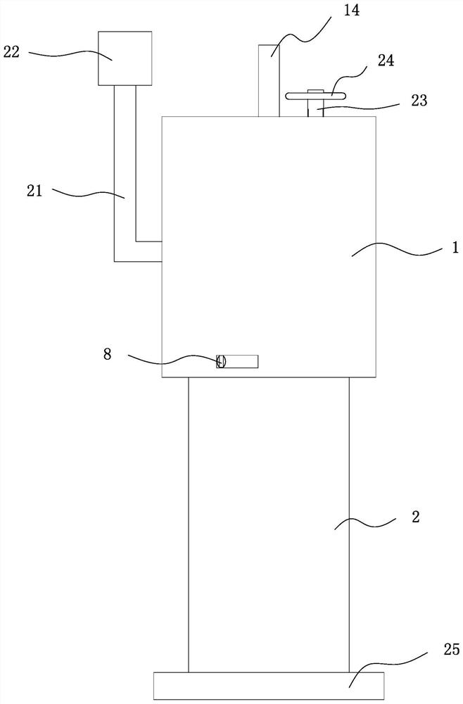
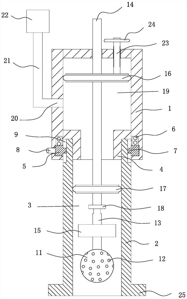
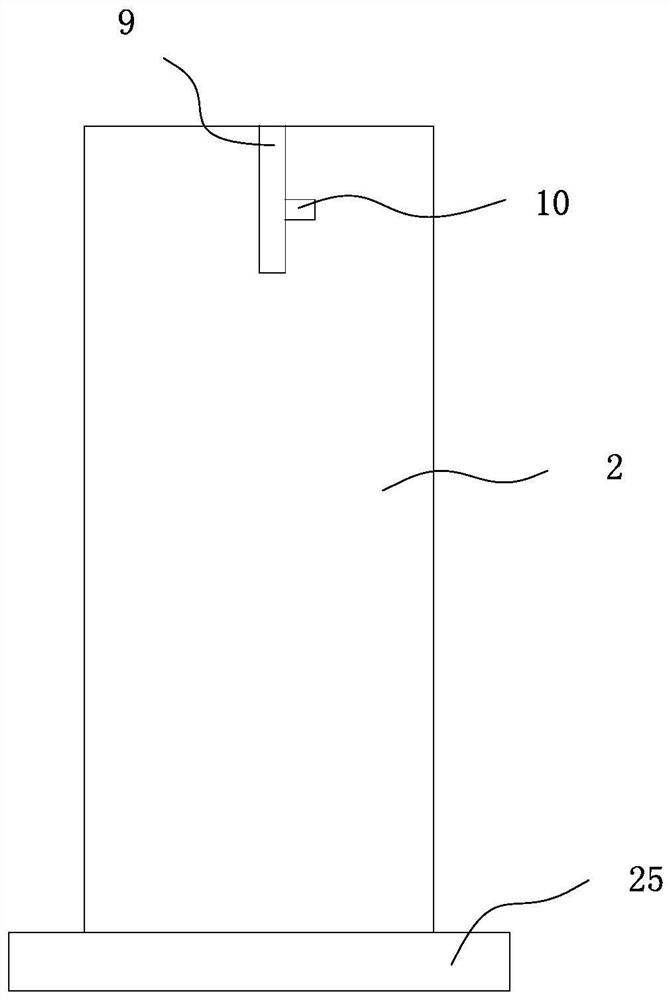
[0015] refer to figure 1 , figure 2 and image 3 As shown, an anti-shrinkage cavity resin sand mold riser device includes a hollow upper part 1 and a lower part 2 in a tubular structure. The upper part 1 and the lower part 2 are clamped and connected, and a through cavity 3 is formed inside. Specifically , the inner surface of the upper part 1 and near the lower end are provided with an embedding groove 4 for the insertion of the lower part 2, and the upper part 1 is rotatably provided with an annular block 5 on the side wall of the embedding groove 4, and the annular block 5 A torsion spring 6 is provided between the block 5 and the upper part, and the side of the annular block 5 facing the embedding groove 4 is outwardly provided with a clamping block 7, and the side of the annular block 5 away from the e


PUM


Abstract

The invention provides an anti-shrinkage resin sand mould riser device. The anti-shrinkage resin sand mould riser device comprises an upper part and a lower part which are hollow and are of tubular structures, the upper part and the lower part are connected in a clamping ode, a through accommodating cavity is formed in the upper part and the lower part, and a pressurizing exhaust mechanism convenient for exhaust and pressurizing is arranged in the accommodating cavity. An installation base used for being installed on a mold is arranged on the lower end of the lower part.

Description


Claims


Application Information

Patent Timeline
Owner 沪航科技集团有限公司
Why Eureka
Try Eureka