Supporting claw, airlock chamber and plasma processing device host platform

A plasma, host platform technology, applied in electrical components, conveyor objects, transportation and packaging, etc., can solve the problems of collision or friction, more serious particle pollution, etc., to prevent the generation of particles, optimize the performance of particles, easy-to-achieve effects

Pending Publication Date: 2020-12-11
ADVANCED MICRO FAB EQUIP INC CHINA
View PDF7 Cites 0 Cited by
  • Summary
  • Abstract
  • Description
  • Claims
  • Application Information

AI Technical Summary

Problems solved by technology

When the mechanical arm 70 placed the wafer 10 in the airlock chamber 20, the mechanical arm 70 moved downwards, and the O-ring 71 stuck on the wafer 10 would completely break away fro

Method used


Image

  • Supporting claw, airlock chamber and plasma processing device host platform
  • Supporting claw, airlock chamber and plasma processing device host platform
  • Supporting claw, airlock chamber and plasma processing device host platform

Examples


Embodiment Construction

[0026] The specific implementation manner of the present invention will be described in more detail below with reference to schematic diagrams. Advantages and features of the present invention will be apparent from the following description and claims. It should be noted that all the drawings are in a very simplified form and use imprecise scales, and are only used to facilitate and clearly assist the purpose of illustrating the embodiments of the present invention.

[0027] In the interest of clarity, not all features of an actual embodiment are described. In the following description, well-known functions and constructions are not described in detail since they would obscure the invention with unnecessary detail. It should be appreciated that in the development of any actual embodiment, numerous implementation details must be worked out to achieve the developer's specific goals, such as changing from one embodiment to another in accordance with system-related or business-relat


PUM

PropertyMeasurementUnit
Thicknessaaaaaaaaaa

Abstract

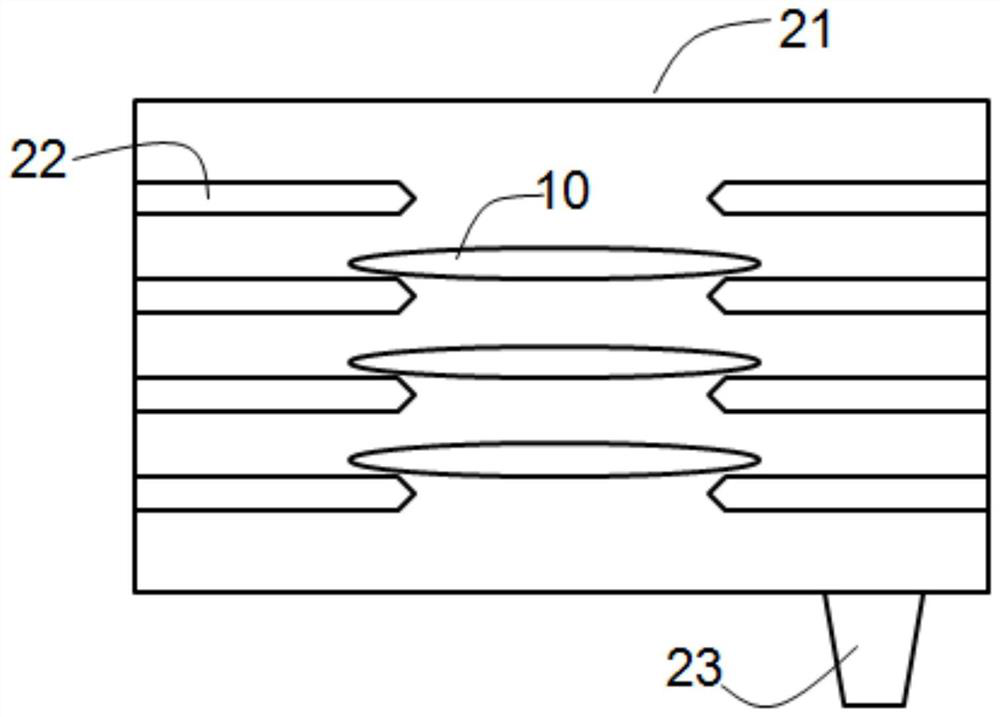
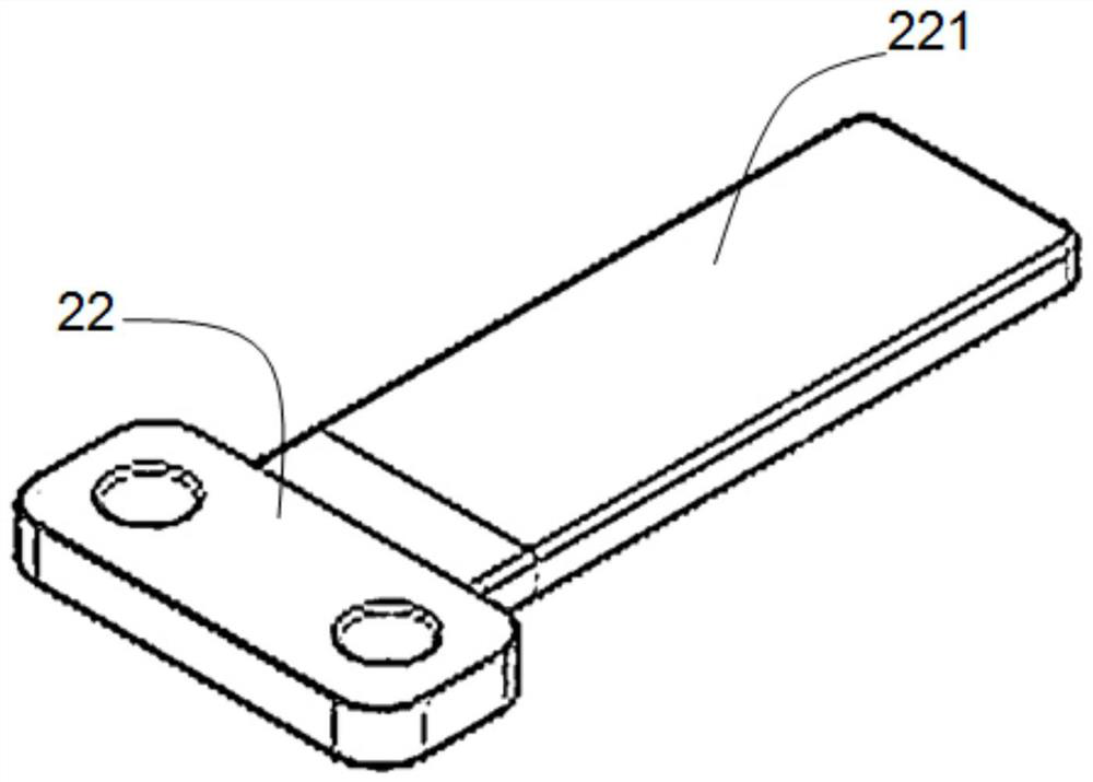
The invention discloses supporting claws, an airlock chamber and a plasma processing device host platform. The two paired supporting claws are in contact with the edge part of a wafer so as to supportthe wafer; each supporting claw comprises a soft wear-resistant material, and the soft wear-resistant material is arranged on the supporting claw and used for reducing or avoiding particles generatedwhen the wafer makes contact with the supporting claw. According to the invention, the soft wear-resistant material is arranged on the supporting claws, so that the soft contact between the supporting claws and the wafer is realized, the friction generated by the hard contact between the silicon wafer and the supporting claws is effectively avoided, the generation of particles can be prevented, and the defect rate of the wafer is greatly reduced.

Description


Claims


Application Information

Patent Timeline
Owner ADVANCED MICRO FAB EQUIP INC CHINA
Why Eureka
Try Eureka