Continuous mixing reactor

A technology of mixing reactor and reaction chamber is applied in the field of mechanical manufacturing and processing, which can solve the problems of long time and uneven mixing.

Pending Publication Date: 2021-05-18
东莞市星东升实业有限公司
View PDF0 Cites 0 Cited by
  • Summary
  • Abstract
  • Description
  • Claims
  • Application Information

AI Technical Summary

Problems solved by technology

[0003] The purpose of the present invention is to provide a continuous mixing reactor for the defects and deficiencies of the prior art, which can realize high-precision mixing of high-viscosity materials, and solve the problem of batch type, long time, uneven mixing, etc. of the existing equipment. problems, to achieve online continuous production

Method used


Image

  • Continuous mixing reactor
  • Continuous mixing reactor
  • Continuous mixing reactor

Examples


Example Embodiment

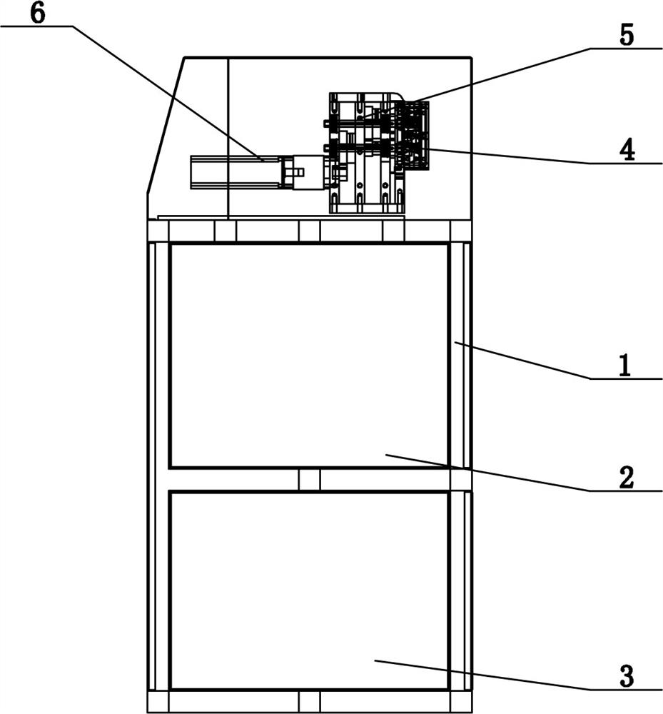
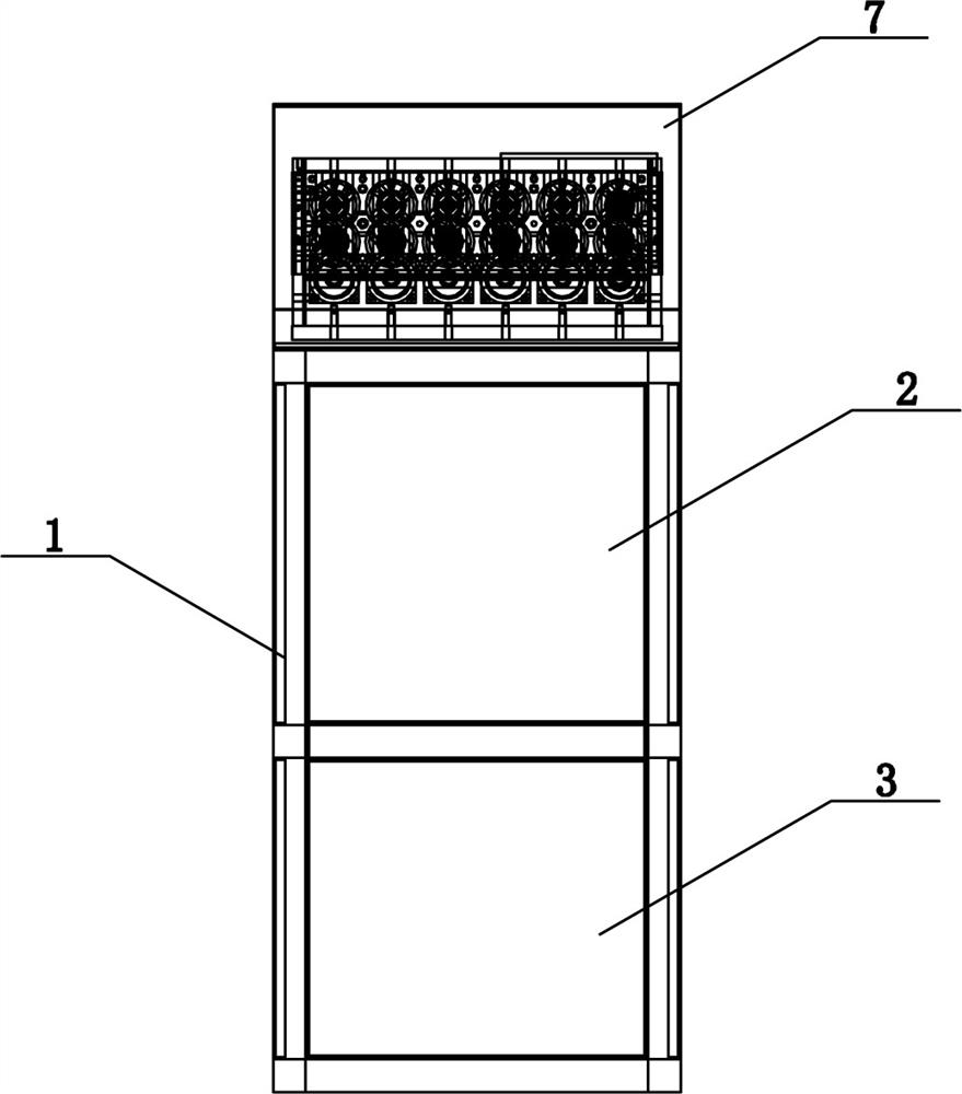
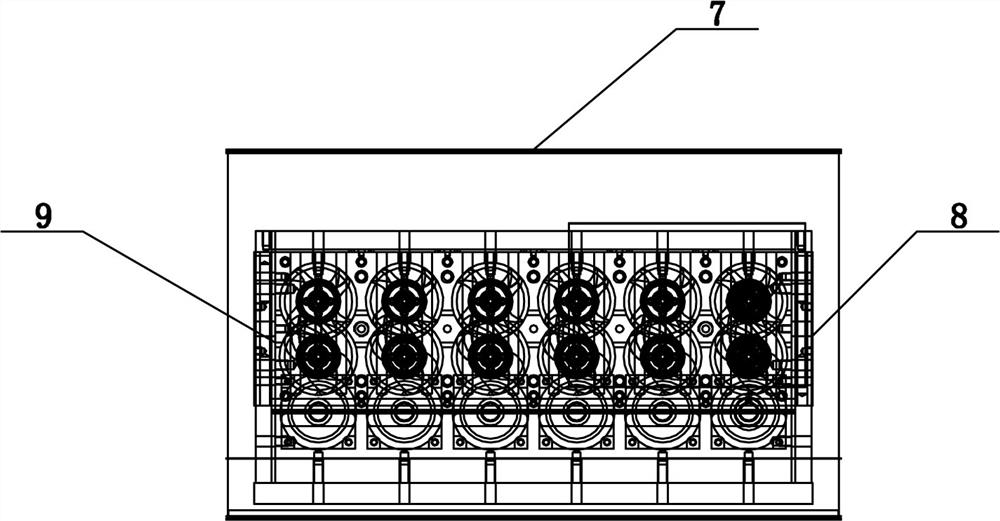
[0017]SeeFigure 1 - Figure 4As shown, the technical solution employed in this particular embodiment is: it includes a host frame 1, an electronically control system 2, a cooling lubricating system 3, a reaction chamber 4, a transmission 5, a servo motor 6, a mixed stirring mechanism 7, a material inlet 8, The material outlet 9, the upper rotor 10, the lower rotor 11; the internal portion of the main frame 1 is mounted above the internal control system 2, and the cooling lubrication system 3 is mounted below the electron control system 2, and the reactive cavity 4 is provided on the electron control system 2. The transmission 5 is electrically connected to the servo motor 6 and is connected to the reaction chamber 4; the main frame 1 is provided with a mixed stirring mechanism 7, and the left and right sides of the mixed stirring mechanism 7 are material inlet 8, material outlet 9, mixed stirring mechanism, respectively. 7 The upper rotor 10 and the lower rotor 11 for the stirred materi


PUM


Abstract

The invention discloses a continuous mixing reactor and relates to the technical field of mechanical manufacturing and processing. The continuous mixing reactor comprises a main machine frame, an electric control system, a cooling and lubricating system, a reaction cavity, a gearbox, a servo motor, a mixing and stirring mechanism, a material inlet, a material outlet, an upper rotor and a lower rotor, the electric control system is installed on the upper portion of the interior of the main machine frame, the cooling and lubricating system is installed below the electric control system, the reaction cavity is formed in the electric control system, and the gearbox is electrically connected with the servo motor and connected with the reaction cavity. A mixing and stirring mechanism is arranged above the main machine frame; after the technical scheme is adopted, the high-precision mixing device has the beneficial effects that high-viscosity materials can be mixed at high precision, the problems of batch type, long time, non-uniform mixing and the like of existing equipment are solved, and online continuous production is realized.

Description


Claims


Application Information

Patent Timeline
Owner 东莞市星东升实业有限公司
Why Eureka
Try Eureka