Automotive trim atmosphere lamp structure

A technology for automotive interior and ambient lighting, which is applied in the field of light guide systems for automotive interior ambient lighting, and can solve problems such as inability to achieve a contrast effect, single light, and complex structure.

Inactive Publication Date: 2021-06-29
NINGBO HUAKAI ELECTRONICS TECH CO LTD
View PDF0 Cites 2 Cited by
  • Summary
  • Abstract
  • Description
  • Claims
  • Application Information

AI Technical Summary

Problems solved by technology

However, the structure of this ambient light is complicated, and th

Method used


Image

  • Automotive trim atmosphere lamp structure
  • Automotive trim atmosphere lamp structure
  • Automotive trim atmosphere lamp structure

Examples


Embodiment Construction

[0038] In order to further explain the technical means and effects of the present invention to achieve the intended purpose of the invention, the specific implementation, structure, features and effects of the present invention will be described in detail below in conjunction with the accompanying drawings and preferred embodiments.

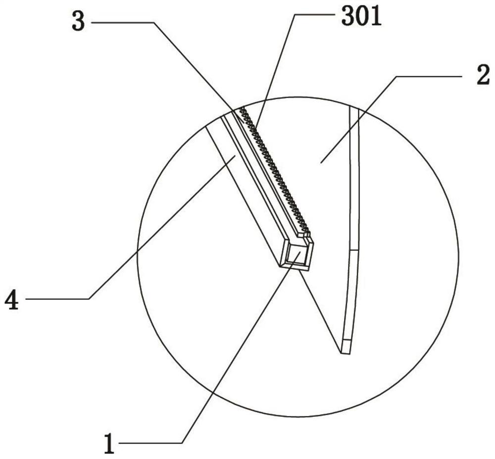
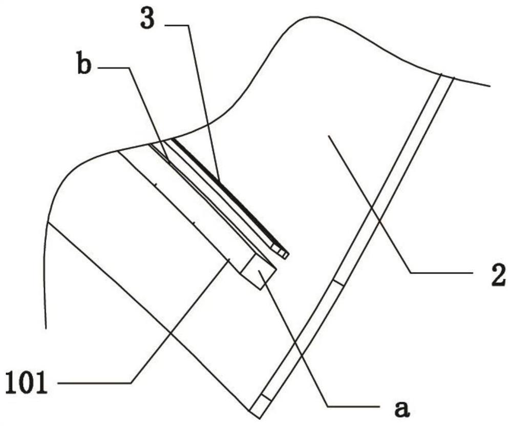
[0039] Such as figure 1 , figure 2 with image 3 As shown, a car interior ambient light structure includes a light guide body 1, a shading plate 3, an incident surface a, a refraction surface b, and an illuminated surface 2 arranged in sequence. The refraction surface and the exit surface b are the light guide body 1 The incident surface a is an end surface perpendicular to both the incident surface a and the refraction surface on the light guide body 1 . The light source is set near the incident surface a, and the shading plate 3 is located near the exiting surface b; the shading plate 3 and the illuminated surface 2 are vertically arranged, and


PUM


Abstract

The invention relates to an automotive trim atmosphere lamp structure which comprises a light guide main body, wherein the light guide main body is light-transmitting and is used for transmitting light from a light source, the surface, directly irradiated by a light source, of the light guide main body is an incident surface, and the emergent direction of the light source is an emergent surface; and a light shielding plate positioned on one side of the emergent surface on the light guide main body, wherein light guide teeth are arranged on the light guide main body; when the light source irradiates the light guide body, light passes through the light guide teeth to form refracted light, and the refracted light irradiates an irradiated surface. The structure has the advantages that the light guide teeth are designed, the shapes of the light guide teeth and the distance between the adjacent light guide teeth are changed, and the light shielding effect of the light shielding plate is matched, so that ray light which is unique in shape and different in brightness is formed, and the effect of heightening the atmosphere in an automobile is better achieved.

Description


Claims


Application Information

Patent Timeline
Owner NINGBO HUAKAI ELECTRONICS TECH CO LTD
Why Eureka
Try Eureka