Cement-based slurry stirring system
A mixing system and base slurry technology, applied in cement mixing devices, liquid batching supply devices, batching weighing instruments, etc., can solve the problems of reducing production efficiency, manual measurement, waste of manpower and material resources, etc., and achieve the effect of improving production efficiency
- Summary
- Abstract
- Description
- Claims
- Application Information
AI Technical Summary
Benefits of technology
Problems solved by technology
Method used
Image

Examples
Embodiment 1
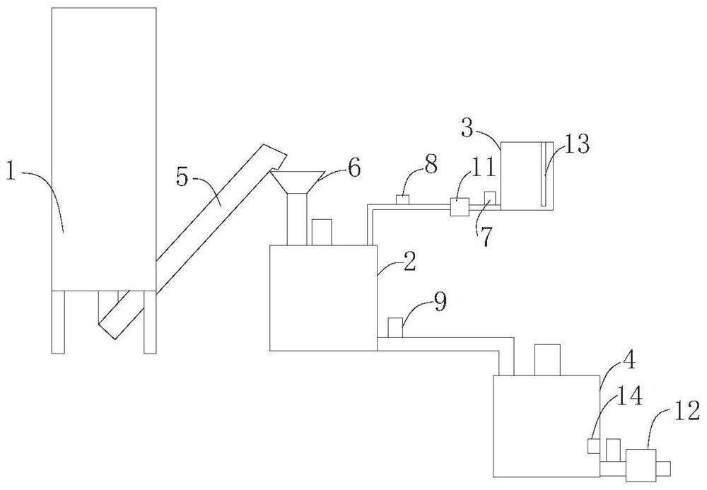
[0051] like figure 1 As shown, the present invention provides a cement-based slurry mixing system, comprising a cement silo 1, a mixer 2, a water tank 3, a storage tank 4, and a controller. 5. Convey the cement to the weighing hopper device 6, which is located above the mixer 2. The feeding port of the weighing hopper device 6 is connected with the feeding port of the mixer 2, and the water outlet of the water tank 3 is connected to the water pump 11 through a water pipe. The water inlet of the water pump 11 is connected with the water inlet of the mixer 2 through a water pipe, and the water pipe between the water outlet of the water tank 3 and the water pump 11 is provided with a first electromagnetic valve 7, and the water outlet of the water pump 11 is connected with the mixer 2 The water pipe between the water inlets is provided with a flow sensor 8, the mixer 2 is located above the storage box 4, the outlet of the mixer 2 is connected with the inlet of the storage box 4 thro
Embodiment 2
[0054] like figure 1 As shown, the difference between this embodiment and the above-mentioned embodiments is that a water level sensor 13 is provided in the water tank 3, a density sensor 14 is provided in the storage tank 4, and both the water level sensor 13 and the density sensor 14 are connected to the controller. The water level sensor 13 is used to measure the water level in the water tank 3. When the water level in the water tank 3 is too low, the controller will send an alarm prompt to replenish water in the water tank 3. The density sensor 14 is used to detect the density of the cement-based slurry in the storage tank 4. And transmit the signal to the controller to achieve the purpose of real-time monitoring the quality of cement-based slurry.
[0055] In some embodiments of the invention, the controller is a PLC controller.
[0056] It can be understood that the PLC controller can conveniently and quickly realize device connection, which is beneficial to program settin
Embodiment 3
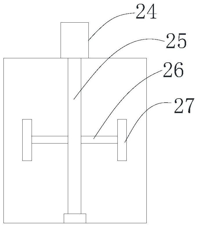
[0058] like figure 1 , figure 2 , image 3 As shown, the difference between this embodiment and Embodiment 1 is:
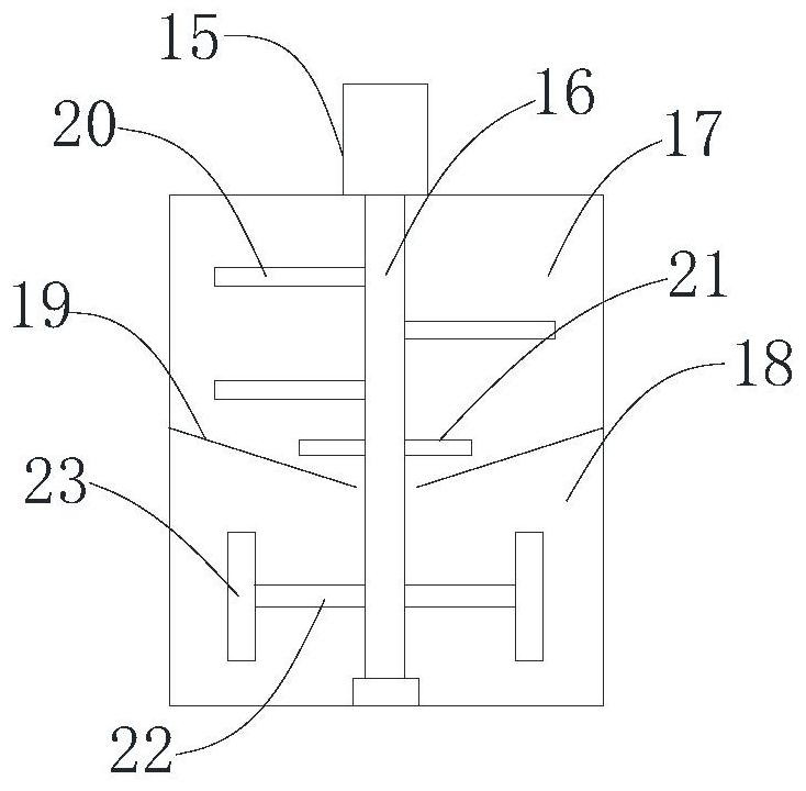
[0059] In some embodiments of the present invention, the agitator 2 includes an upper agitation chamber 17 and a lower agitation chamber 18, and the upper agitation chamber 17 and the lower agitation chamber 18 are separated by a conical partition 19 with an opening at the bottom, and the first agitator 2 The motor 15 is connected with a first stirring shaft 16 , and the first stirring shaft 16 passes through the bottom opening of the conical partition 19 .
[0060] It can be understood that the mixer 2 includes an upper mixing chamber 17 and a lower mixing chamber 18. After the cement and water are mixed in the upper mixing chamber 17, they are mixed and stirred through the lower mixing chamber 18 to achieve the purpose of uniform mixing of cement and water. The upper mixing chamber 17 and the lower mixing chamber 18 are separated by a conical partition 19 with
PUM
 Abstract
Description
Claims
Application Information
 - R&D Engineer
- R&D Manager
- IP Professional
- Industry Leading Data Capabilities
- Powerful AI technology
- Patent DNA Extraction
Browse by: Latest US Patents, China's latest patents, Technical Efficacy Thesaurus, Application Domain, Technology Topic.
© 2024 PatSnap. All rights reserved.Legal|Privacy policy|Modern Slavery Act Transparency Statement|Sitemap