Relay

A relay and dynamic contact technology, which is applied in the direction of relays, electromagnetic relays, detailed information of electromagnetic relays, etc., can solve the problem of high contact resistance of relays, achieve the effect of reducing contact resistance and suppressing temperature rise

Pending Publication Date: 2021-10-22
ORMON CORPORATION
View PDF1 Cites 0 Cited by
  • Summary
  • Abstract
  • Description
  • Claims
  • Application Information

AI Technical Summary

Problems solved by technology

Therefore, in a structure in which there are two sets of fixed contacts and movable con

Method used


Image

  • Relay
  • Relay
  • Relay

Examples


Example Embodiment

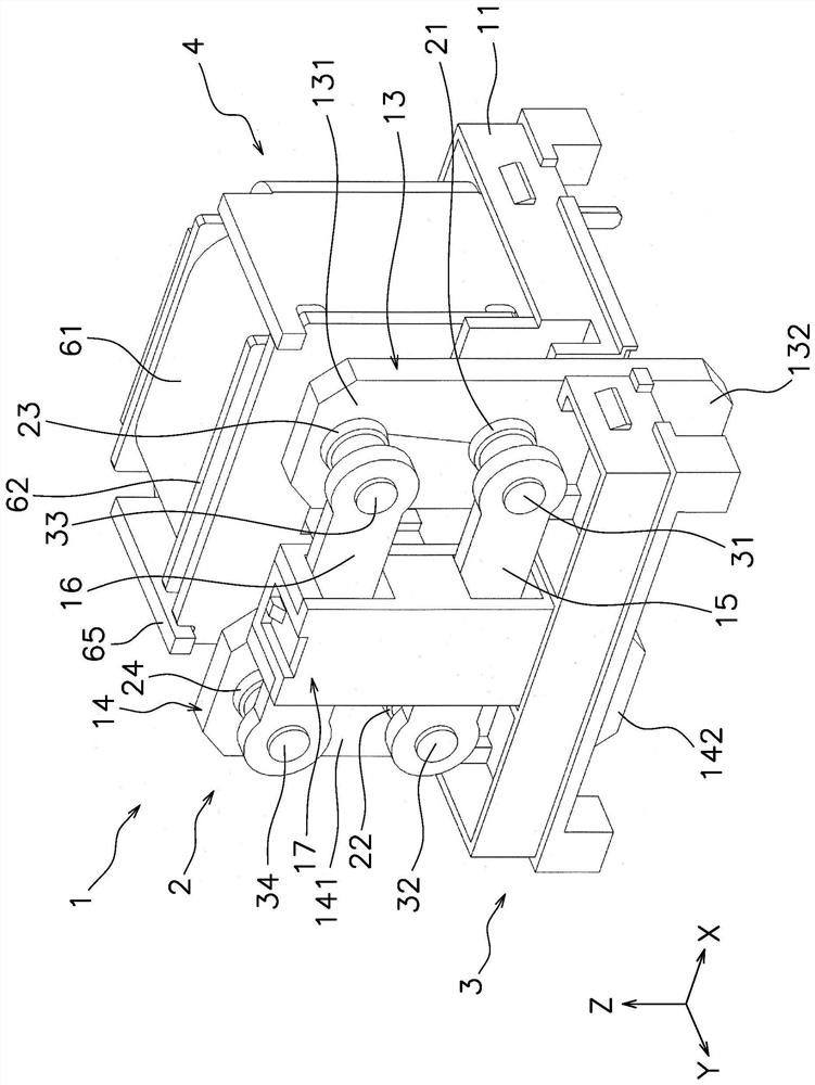
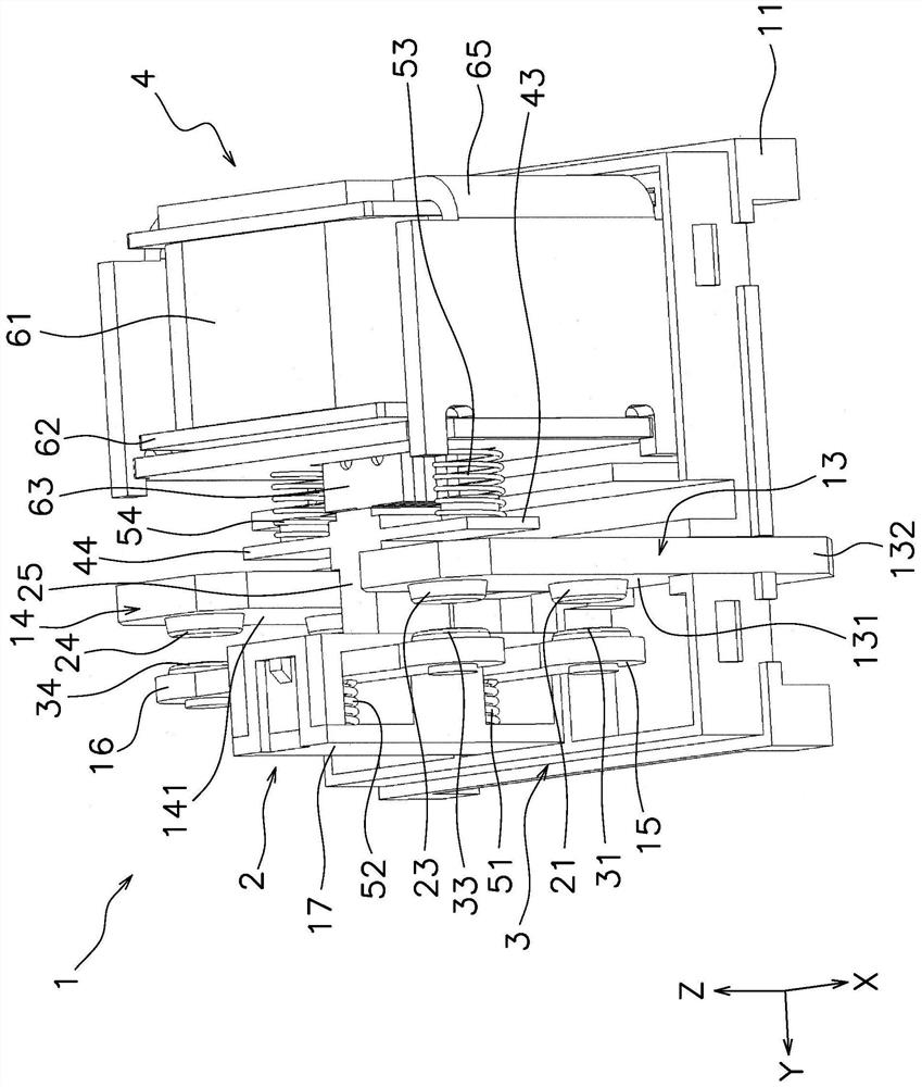
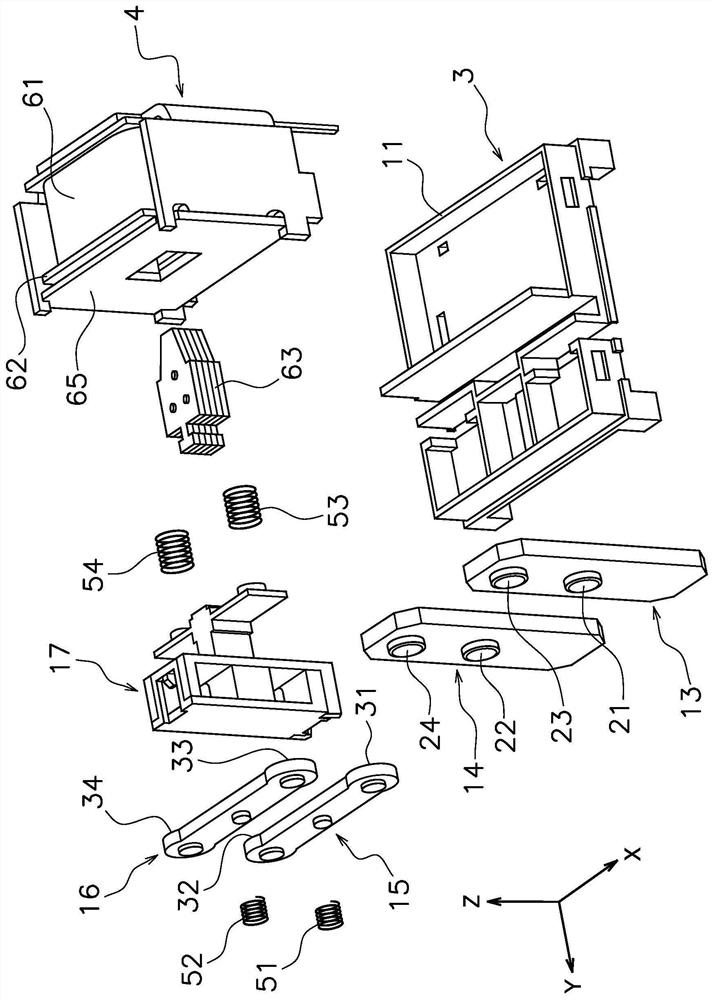
[0030] Hereinafter, the relay 1 of the embodiment will be described with reference to the drawings. figure 1 and figure 2 It is a perspective view of the relay 1 of embodiment. image 3 It is an exploded perspective view of the relay 1 . Figure 4 is a side view of relay 1. Figure 5 This is the front view of Relay 1.

[0031] like Figure 1 to Figure 5 As shown, the relay 1 includes a contact device 2 , a housing 3 , and a drive device 4 . The contact device 2 and the drive device 4 are arranged in the housing 3 . The housing 3 includes the base 11 and Figure 4 Housing 12 shown. In addition, in Figure 4 In the figure, the base 11 and the case 12 are shown in cross section. exist Figure 1 to Figure 3 as well as Figure 5 , the housing 12 is omitted.

[0032] In addition, in the following description, the direction in which the contact device 2 and the drive device 4 are arranged with respect to the base 11 is defined as the upper direction, and the opposite direct


PUM


Abstract

In the present invention, a first and second movable contact point are connected to a first movable contactor. A second movable contactor is separate from the first movable contactor. A third and fourth movable contact point are connected to the second movable contactor. A drive device moves the first movable contactor and the second movable contactor by a movable core 63 moving by magnetism emitted from a coil. The first movable contactor and the second movable contactor are mutually electrically connected in parallel to a first fixed terminal and a second fixed terminal, with the first through fourth movable contact points making contact respectively with first through fourth fixed contact points.

Description


Claims


Application Information

Patent Timeline
Owner ORMON CORPORATION
Why Eureka
Try Eureka