Tin soldering equipment for wiring terminal and enameled aluminum wire on straight stator

A technology for connecting terminals and arranging stators, applied in the field of machinery, can solve the problems of waste of manpower, low efficiency of manual soldering, and inability to guarantee welding quality, and achieve the effect of improving production efficiency

Pending Publication Date: 2021-11-26
浙江理工大学上虞工业技术研究院有限公司 +2
View PDF0 Cites 0 Cited by
  • Summary
  • Abstract
  • Description
  • Claims
  • Application Information

AI Technical Summary

Benefits of technology

This patented technology allows automatic removal of an insulating layer covering certain parts of a motor's rotating part called the core while maintaining good electrical contact with other components like metal leads used during manufacturing processes. It also simplifies the process by allowing the rods and cores to move smoothly without getting stuck together due to gravity forces when they come into contact again. Additionally, it includes mechanisms to ensure proper alignment of the ropes before applying molten coins onto them. Overall, this innovation makes automated treatment faster and easier than traditional methods.

Problems solved by technology

This patented technical problem addressed in this patents relates to improving the efficient use of labor during the process for producing linear rows of stators made up mostly of copper or iron based materials due to their ease of handling compared to other metals such as silver (Ag) that are commonly used today's industry standard material. Current methods require multiple steps involving human operators and can result in poorly controlled results overall making them difficult to automate efficiently while maintaining consistently reliable performance across different types of wiring configurations.

Method used


Image

  • Tin soldering equipment for wiring terminal and enameled aluminum wire on straight stator
  • Tin soldering equipment for wiring terminal and enameled aluminum wire on straight stator
  • Tin soldering equipment for wiring terminal and enameled aluminum wire on straight stator

Examples


Embodiment Construction

[0031] The present invention will be further described below in conjunction with the accompanying drawings.

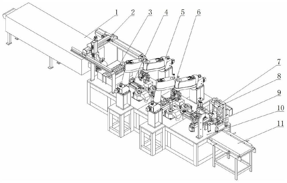
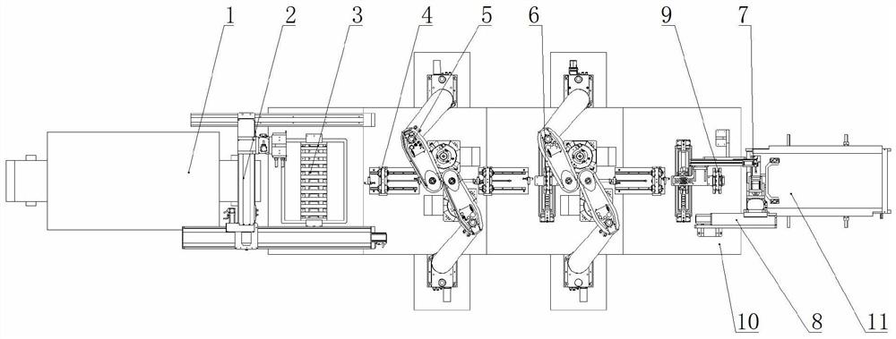
[0032] Such as figure 1 and 2 As shown in the figure, a soldering equipment for connecting terminals on the stator and enamelled aluminum wires in a straight row includes a drying channel belt transmission mechanism 1, a drying channel, a cleaning and feeding mechanism 2, an ultrasonic cleaning box assembly 3, a transfer transition mechanism 1, and a transfer mechanism Transition mechanism 2, transfer transition mechanism 3 4, paint stripping mechanism, soldering mechanism 5, paint remover reagent tank assembly, flux reagent tank assembly 6, flip feeding mechanism 7, handling mechanism 8, feeding tooling 9, base 10 and feeding belt transmission mechanism 11. The transmission belt of the feeding belt transmission mechanism 11 is fixed with multiple vertical partitions arranged equidistantly along the ring of the transmission belt; the feeding tooling 9 is located at the


PUM


Abstract

The invention discloses tin soldering equipment for a wiring terminal and an enameled aluminum wire on a straight stator. A feeding tool is located at the output end of a feeding belt transmission mechanism, and an overturning feeding mechanism and a carrying mechanism are arranged on the two sides of the feeding tool; a paint remover reagent groove assembly is arranged at the output end of the carrying mechanism, and a first transfer transition mechanism is arranged on the side, away from the feeding belt transmission mechanism, of the paint remover reagent groove assembly. Two paint removing mechanisms are arranged at the output end of the first transmission transition mechanism, a scaling powder reagent tank assembly is arranged at the output ends of the paint removing mechanisms, and a second transmission transition mechanism is arranged on the side, away from the paint removing mechanisms, of the scaling powder reagent tank assembly; two tin soldering mechanisms are arranged at the output end of the second transmission transition mechanism, and a third transmission transition mechanism is arranged at the output end of a tin soldering mechanism. An ultrasonic cleaning box assembly is arranged at the output end of the third transmission transition mechanism, and a cleaning and discharging mechanism is arranged between the ultrasonic cleaning box assembly and the input end of a drying tunnel belt transmission mechanism arranged in a drying tunnel. According to the tin soldering machine, tin soldering of the wiring terminal and the aluminum wire of the straight stator is automatically achieved, and the tin soldering quality is stable.

Description


Claims


Application Information

Patent Timeline
Owner 浙江理工大学上虞工业技术研究院有限公司
Why Eureka
Try Eureka