Laser acceleration proton beam homogenization method and device

A proton beam and homogenization technology, applied in accelerators, electrical components, etc., can solve the problem of low current intensity of proton beams and achieve the effect of uniformity optimization

Pending Publication Date: 2022-05-13
PEKING UNIV +1
View PDF5 Cites 0 Cited by
  • Summary
  • Abstract
  • Description
  • Claims
  • Application Information

AI Technical Summary

Problems solved by technology

[0005] However, the current intensity of the proton beam driven by the laser is low, so it is not suitable to use the above method

Method used


Image

  • Laser acceleration proton beam homogenization method and device
  • Laser acceleration proton beam homogenization method and device
  • Laser acceleration proton beam homogenization method and device

Examples


Example Embodiment

[0041] Below in conjunction with the accompanying drawings, the present invention will be further described through specific embodiments.

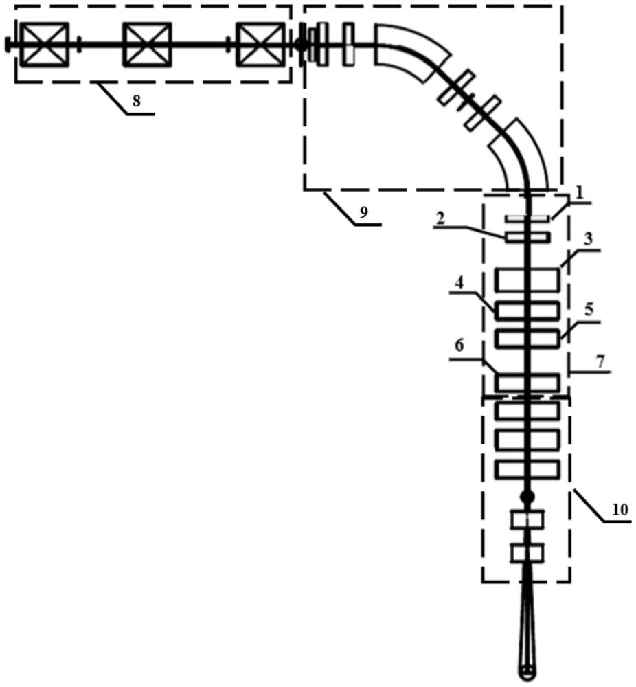
[0042] like figure 1 As shown, the laser accelerated proton beam homogenization system based on nonlinear high-order magnets in this embodiment includes: a beam collection section 8, an energy selection section 9, a beam homogenization transmission line 7 and a beam shaping transmission line 10; The beam of ideal energy passes through the beam collection section and the energy selection section to obtain the proton beam of ideal energy; the lateral distribution of the proton beam of ideal energy is Gaussian distribution, and the ideal energy particles pass through the beam homogenization transmission line to complete the uniform distribution of the beam. Finally, through the beam shaping transmission line, a uniform proton beam with a rectangular cross-section is obtained, which is used for the later step scanning treatment of cancer; wherein


PUM


Abstract

The invention discloses a laser acceleration proton beam homogenization method and device. According to the beam homogenization transmission line, a combination of a quadrupole magnet and a high-order magnet is adopted, beam homogenization operation is carried out on a proton beam in the X direction and the Y direction, and the cross section of the proton beam is gradually changed into a rectangular beam which is uniformly distributed; according to the method, a control method that a traditional cancer treatment accelerator uses continuous scanning and dose superposition is abandoned, an original Gaussian distribution beam bunch is optimized into a relatively regular rectangle with uniformly distributed particles, and the application of rectangular beam spots enables a scanning and superposition irradiation area to cover a focus without overlapping; the utilization rate of particles generated by laser can be maximized, and the particles can be converted into a rectangular beam which is easier to control, so that step scanning can be conveniently carried out in the treatment process, and an irradiated focus can be ensured to receive uniform and controllable dose irradiation; according to the invention, the high-order magnet is adopted to complete the optimization of the uniformity of the laser-driven proton beam, and the project of a laser-driven proton treatment device is promoted.

Description


Claims


Application Information

Patent Timeline
Owner PEKING UNIV
Why Eureka
Try Eureka