Position design of alignment marks

A technology for aligning marks and designing structures, which is applied in the direction of photomechanical equipment, pattern surface photolithography, optics, etc. It can solve the problems affecting the correct reflection path of light and affecting the stability, so as to achieve good flatness and improve stability sexual effect

Inactive Publication Date: 2004-06-16
UNITED MICROELECTRONICS CORP
View PDF0 Cites 0 Cited by
  • Summary
  • Abstract
  • Description
  • Claims
  • Application Information

AI Technical Summary

Problems solved by technology

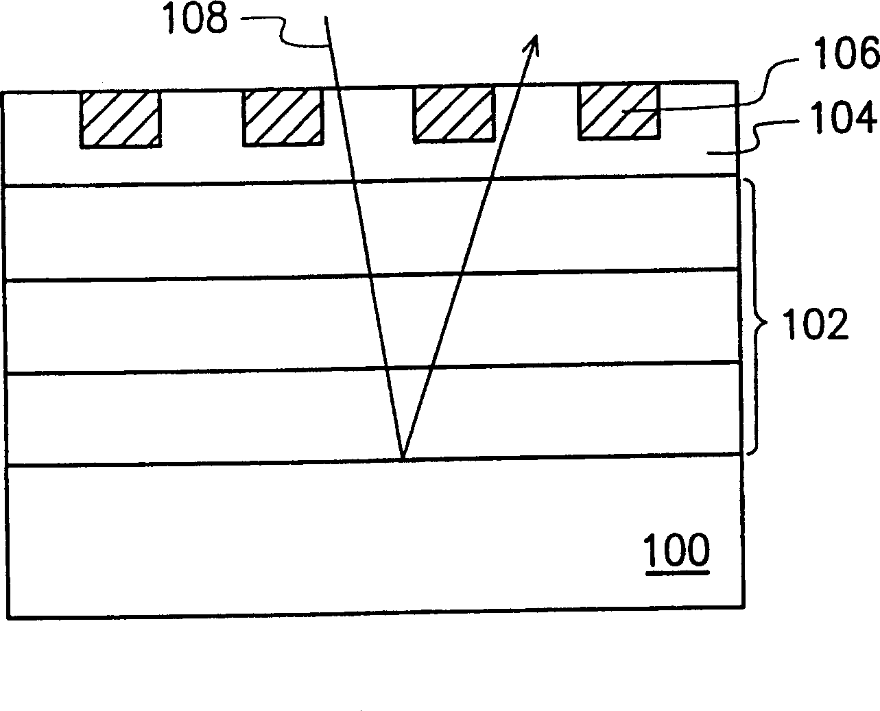
However, the monolithic metal platform has the problem of dishing during the chemical mechanical polishing process. The metal platform that produces the dishing

Method used


Image

  • Position design of alignment marks
  • Position design of alignment marks
  • Position design of alignment marks

Examples


Embodiment Construction

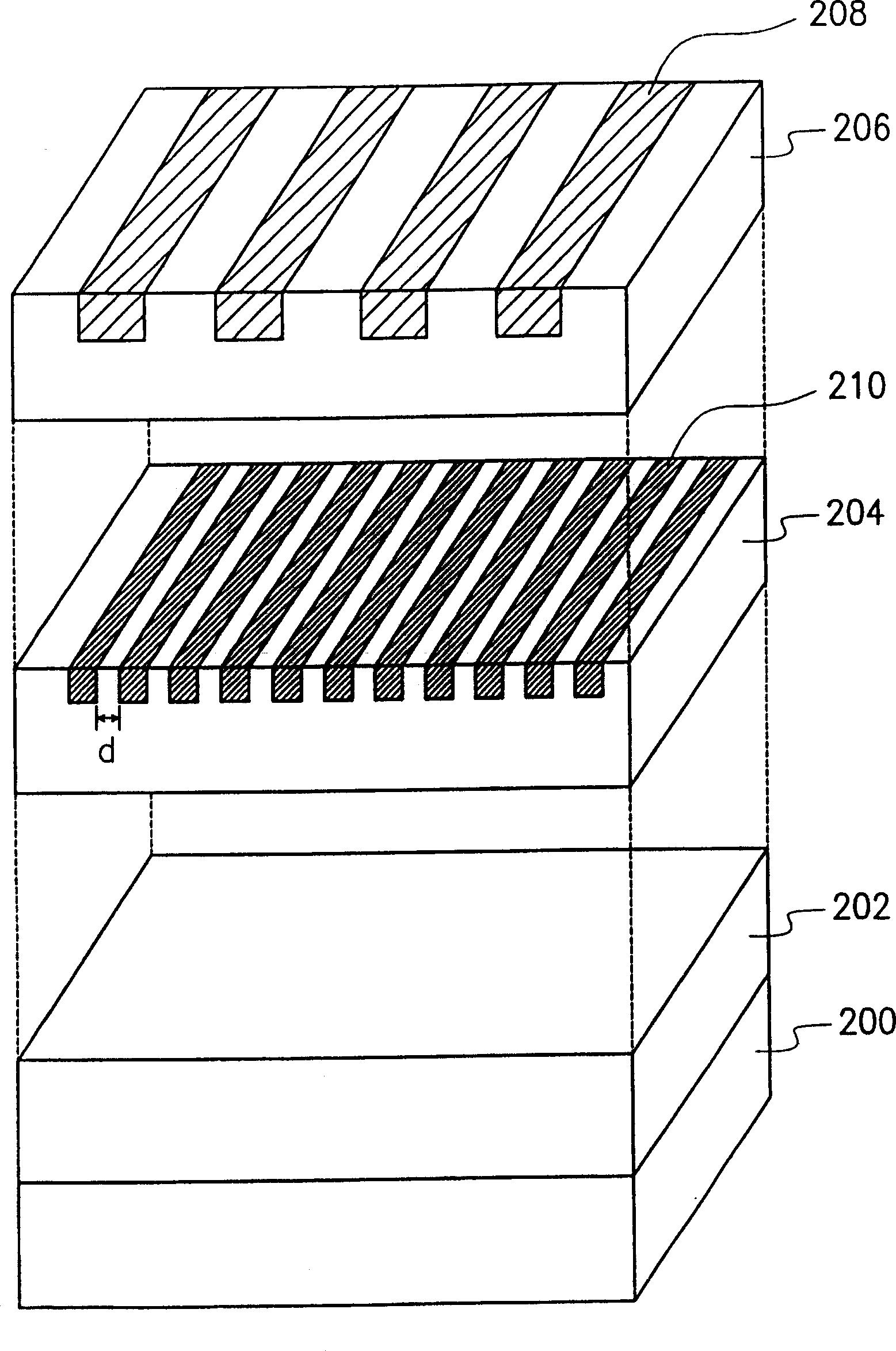
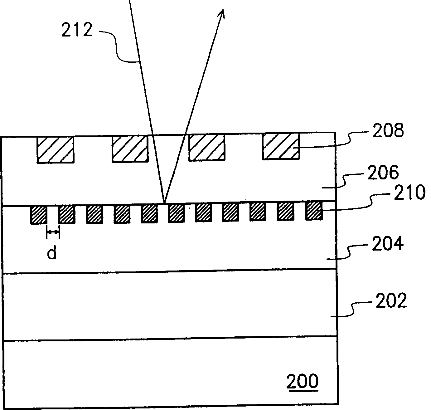
[0024] Please also refer to figure 2 as well as image 3 , figure 2 What is shown is an exploded schematic diagram of the three-dimensional structure of the position design of the non-zero layer alignment mark of the preferred embodiment of the present invention, and image 3 What is shown is a cross-sectional schematic diagram of the positional design of the non-zero layer alignment mark of the preferred embodiment of the present invention.

[0025] Depend on figure 2 and image 3 It can be seen that the alignment mark 208 is disposed in a planarized dielectric layer 206 on the semiconductor substrate 200, and the method for forming the alignment mark 208 is, for example, firstly forming several long lengths with similar positions in the dielectric layer 206. strip-shaped openings (not shown), and metal material is filled in the strip-shaped openings to form non-zero layer alignment marks composed of a plurality of metal lines. Usually, the alignment mark manufacturing p


PUM


Abstract

A position design for alignment mark which is used on the substrate having a multilayered structure, the alignment mark is arranged on the first dielectric layer of the substrate, and a metallic pattern layer is arranged in another dielectric layer below the first dielectric layer, wherein the metallic pattern layer comprises a plurality of bar shaped metal wires, and the distance between the bar shaped metal wires is smaller than the wavelength of light for aligning.

Description


Claims


Application Information

Patent Timeline
Owner UNITED MICROELECTRONICS CORP
Why Eureka
Try Eureka