Switchable magnetic array

Active Publication Date: 2018-07-24
APPLE INC
View PDF30 Cites 6 Cited by
  • Summary
  • Abstract
  • Description
  • Claims
  • Application Information

AI Technical Summary

Benefits of technology

[0014]Moreover, when the third remnant magnetization is in a first direction, the attractive force at the attraction plate is greater than a threshold value. Alternativel

Problems solved by technology

This may reduce the attractive force between the permanent magnets and the electromagnet, which may make the permanent magnets and the electromagnets less effective as a latch.
However, a larger remnant magnetization may increase the risk that the permanent magnets inadvertently damage components or devices that are sensitive to strong magnetic fields, suc

Method used


Image

  • Switchable magnetic array
  • Switchable magnetic array
  • Switchable magnetic array

Examples


Embodiment Construction

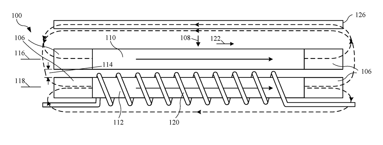
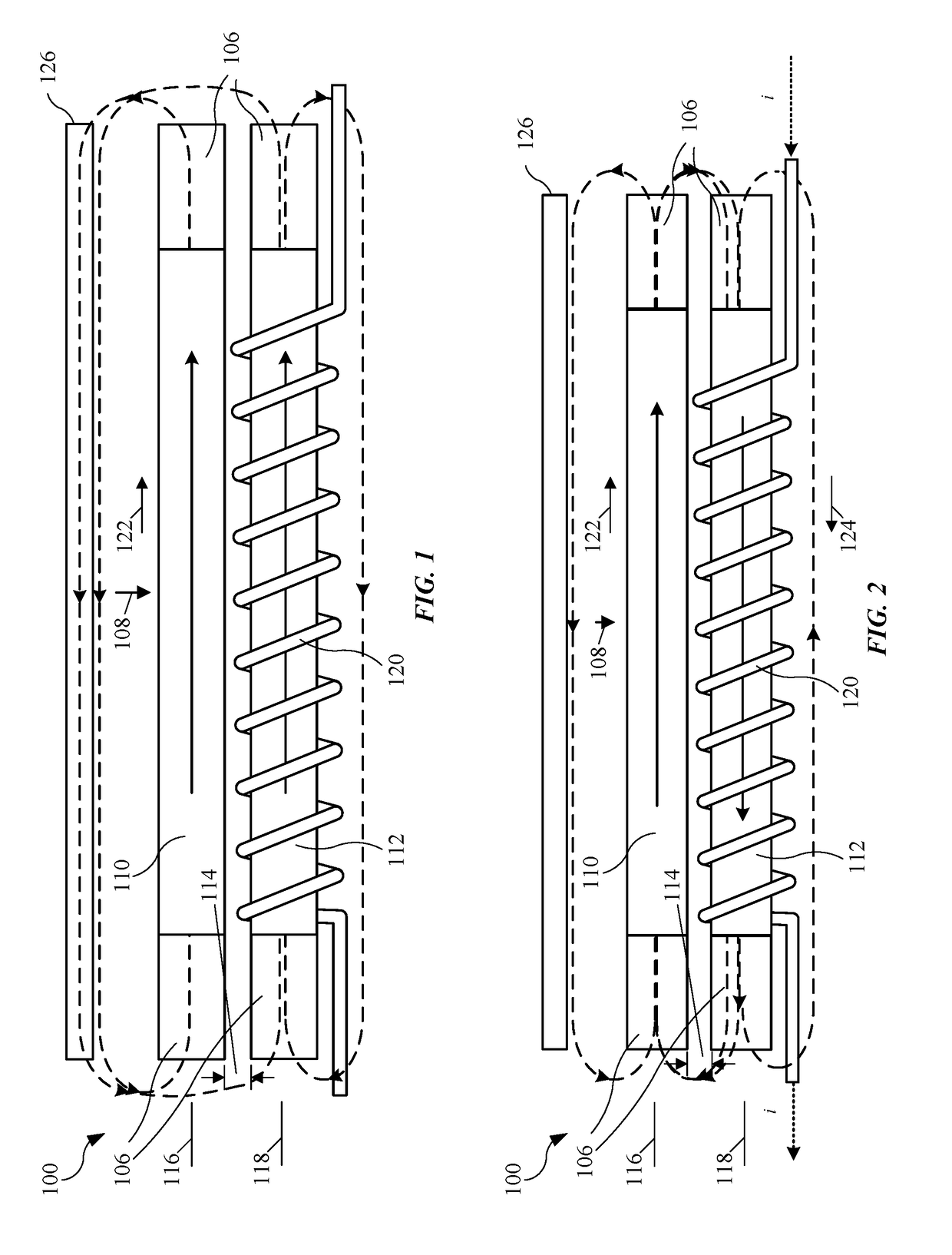
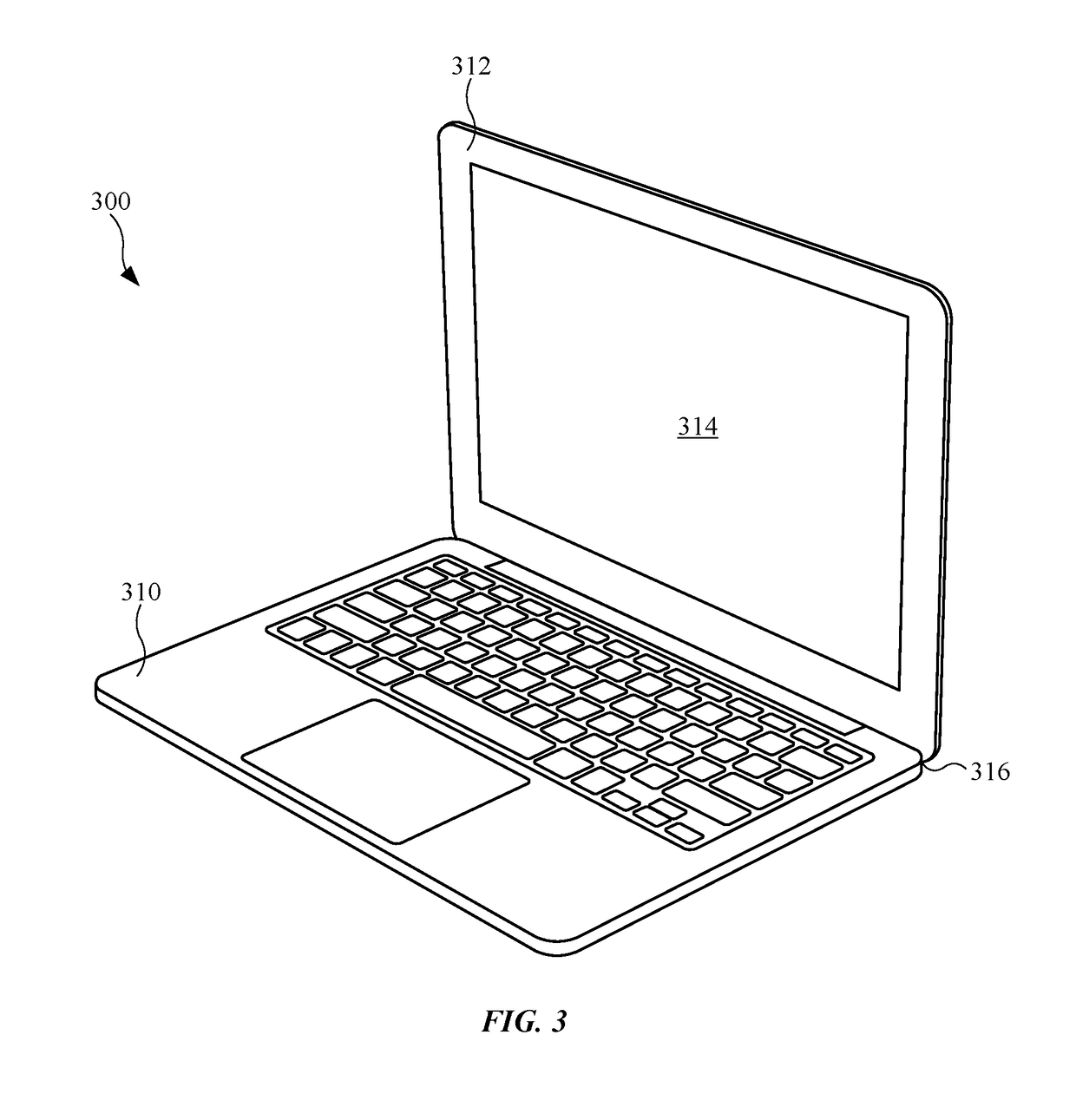
[0039]An electronic device (such as a laptop) may selectively latch a base to a lid using a switchable magnet array. In particular, a drive circuit in the electronic device may apply at least a current pulse to a conductor that generates a magnetic field to reverse a direction of a remnant magnetization in the switchable magnet array. By reversing the direction of the remnant magnetization, the electronic device may selectively increase or decrease a magnetic field generated by the switchable magnet array at an attraction plate in the electronic device. This magnetic field may, in turn, result in an attractive force between the switchable magnet array and the attraction plate, thereby selectively latching the base and the lid when the base and the lid are proximate to each other.

[0040]By allowing the magnetic field produced by the switchable magnet array to be selectively changed, this latching technique may provide a compact, low-power technique for latching components (such as the ba


PUM


Abstract

An electronic device (such as a laptop) may selectively latch a base to a lid using a switchable magnet array. In particular, a drive circuit in the electronic device may apply at least a current pulse to a conductor that generates a magnetic field to reverse a direction of a remnant magnetization in the switchable magnet array. By reversing the direction of the remnant magnetization, the electronic device may selectively increase or decrease a magnetic field generated by the switchable magnet array at an attraction plate in the electronic device. This magnetic field may, in turn, result in an attractive force between the switchable magnet array and the attraction plate, thereby selectively latching the base and the lid when the base and the lid are proximate to each other.

Description


Claims


Application Information

Patent Timeline
Owner APPLE INC
Why Eureka
Try Eureka