Image pickup device and production method thereof
a technology of image pickup and production method, which is applied in the direction of color television, television system, radio control device, etc., can solve the problems of increased thermal expansion coefficient of transparent resin, loss of incident light, and increase of fabrication cost, so as to achieve low cost, high performance of light entry, and low deformation
- Summary
- Abstract
- Description
- Claims
- Application Information
AI Technical Summary
Benefits of technology
Problems solved by technology
Method used
Image

Examples
first embodiment
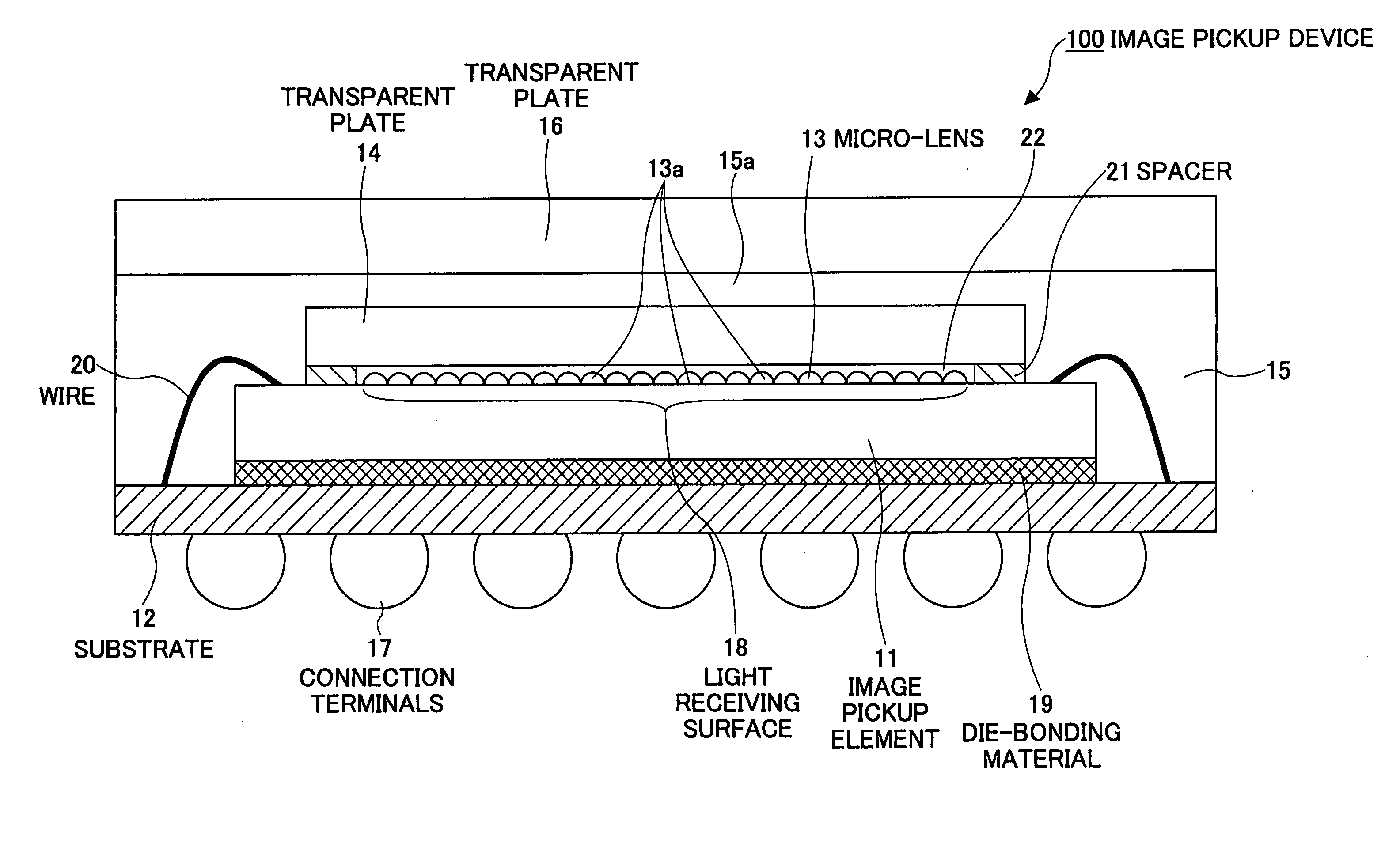
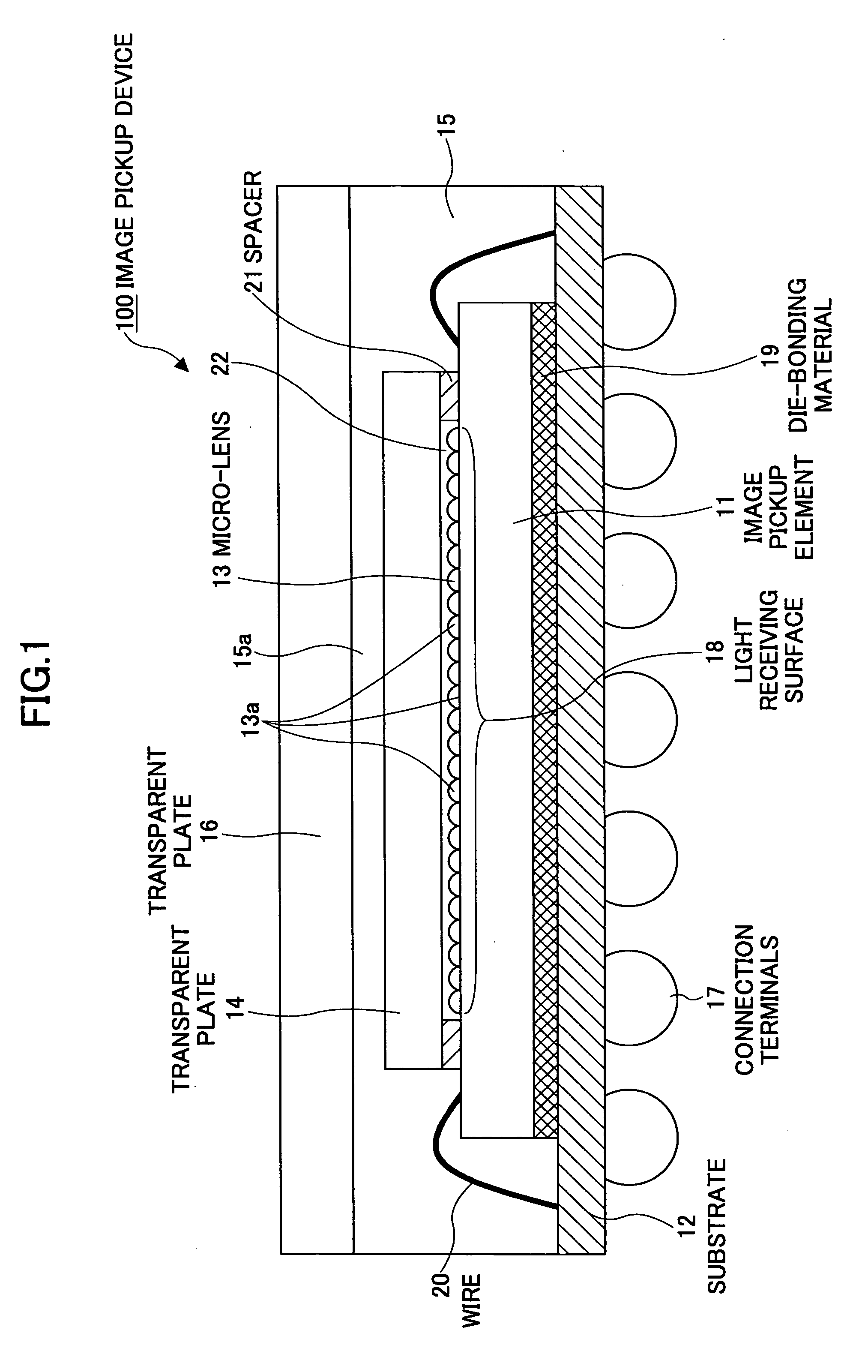
[0056]FIG. 1 is a cross-sectional view of an image pickup device 100 according to a first embodiment of the present invention.
[0057] As illustrated in FIG. 1, the image pickup device 100 includes an image pickup element (light receiving element) 11, a substrate 12, a micro-lens 13, a first transparent plate 14, transparent resin 15, a second transparent plate 16, and external connection terminals 17.
[0058] The upper surface of the image pickup element 11 is the light receiving surface 18, and the image pickup element 11 is mounted and fixed on the substrate 12 through a Die-bonding material 19. Although not illustrated in FIG. 1, a number of photo diodes are arranged in a matrix manner on the light receiving surface 18 of the image pickup element 11, and the micro-lens 13 is arranged on the photo diodes via a not-illustrated color filter layer.
[0059] For example, the color filter layer is formed from a photo resist (a photo sensitive resin) added with a certain pigment, and is segme
second embodiment
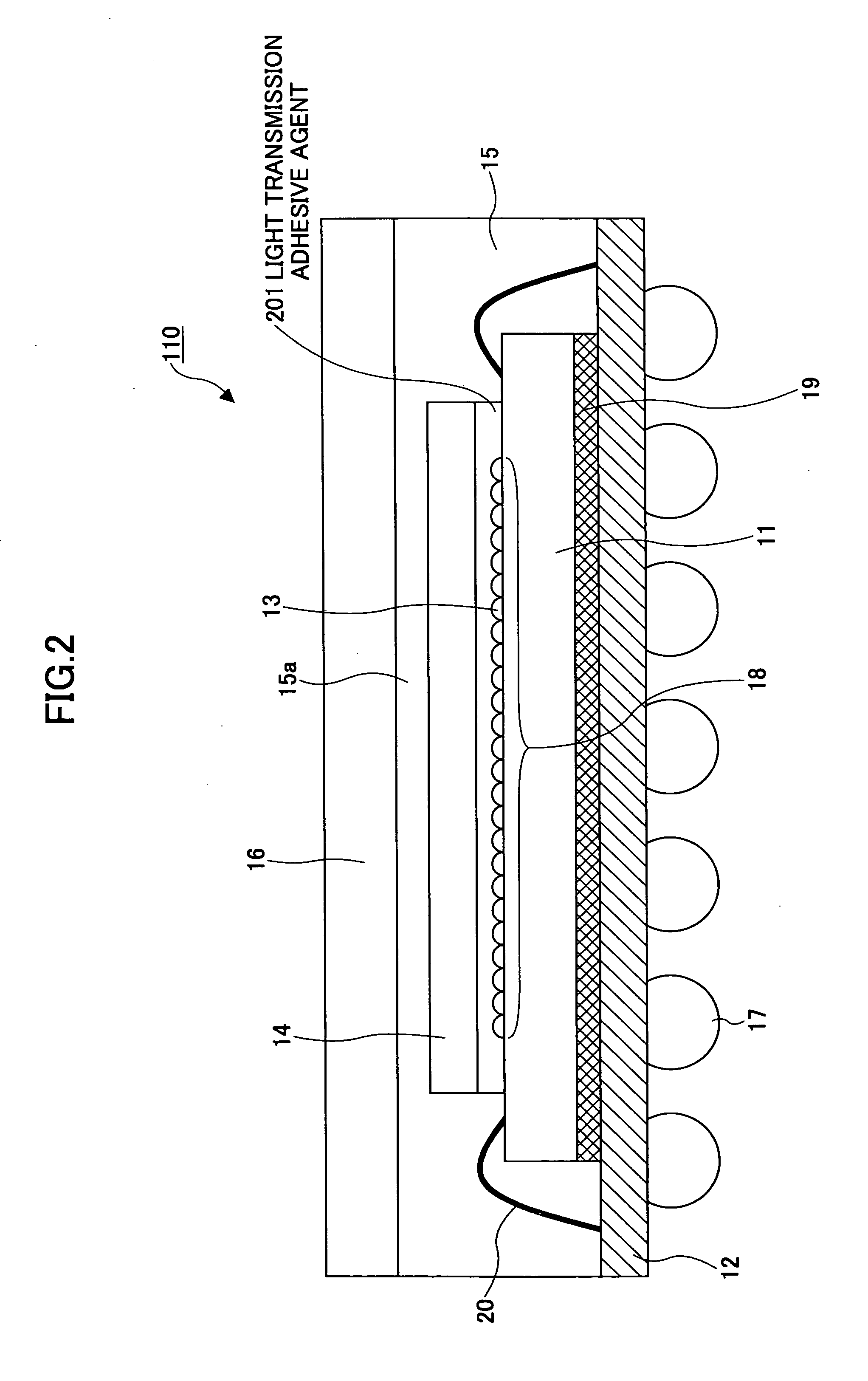
[0088]FIG. 2 is a cross-sectional view of an image pickup device 110 according to a second embodiment of the present invention.
[0089] In the following descriptions and drawings in the present embodiment, and in the subsequent embodiments, the same reference numbers are used for the same elements as those in the first embodiment and FIG. 1, and duplicate descriptions are omitted.
[0090] As illustrated in FIG. 2, the image pickup device 110 is basically the same as the image pickup device 100 except that in the image pickup device 110 of the present embodiment, a light transmission adhesive agent 201 is disposed between the first transparent plate 14 and the image pickup element 11, instead of the air layer 22 in the first embodiment.
[0091] In order to improve light condensing performance, the light transmission adhesive agent 201 is formed from a material having a smaller refractive index than that of the micro-lens 13.
[0092] According to the present embodiment, because there are no
third embodiment
[0093]FIG. 3 is a cross-sectional view of an image pickup device 120 according to a third embodiment of the present invention.
[0094] As illustrated in FIG. 3, in the image pickup device 120, the first transparent plate 14 is directly disposed on the micro-lens 13.
[0095] The first transparent plate 14 is fixed on the image pickup element 11 by an adhesive agent 301. Because there are spaces surrounding individual micro-lenses 13a, air may be introduced into the spaces.
[0096] According to the present embodiment, it is possible to obtain good optical characteristics compared with a structure in which a transparent resin is placed between the first transparent plate 14 and the micro-lens 13. In addition, because the first transparent plate 14 is directly supported by the micro-lens 13, the image pickup device 120 has increased strength against external forces applied from the upper side.
[0097] For convenience, effects of disposing the first transparent plate 14 directly on the micro-le
PUM
 Abstract
Description
Claims
Application Information
 - R&D Engineer
- R&D Manager
- IP Professional
- Industry Leading Data Capabilities
- Powerful AI technology
- Patent DNA Extraction
Browse by: Latest US Patents, China's latest patents, Technical Efficacy Thesaurus, Application Domain, Technology Topic.
© 2024 PatSnap. All rights reserved.Legal|Privacy policy|Modern Slavery Act Transparency Statement|Sitemap