Optical scanner, image forming apparatus, and image forming method

Inactive Publication Date: 2009-07-30
KYOCERA DOCUMENT SOLUTIONS INC
View PDF9 Cites 12 Cited by
  • Summary
  • Abstract
  • Description
  • Claims
  • Application Information

AI Technical Summary

Benefits of technology

[0021]According to the present invention, a timing when the incidence of a laser beam having an emission intensity equal to or higher than the reference emission intensity is detected by the laser beam detector, in short, a start timing of the electrostatic latent image formation controlled by the timing controller for exposure start, can be kept constant, and thus, a position of the electrostatic latent image in the main scanning direction on the photoreceptor can be kept constant.
[0022]Particularly, in an imag

Problems solved by technology

This causes a problem that the position in the main scanning direction of a electro

Method used


Image

  • Optical scanner, image forming apparatus, and image forming method
  • Optical scanner, image forming apparatus, and image forming method
  • Optical scanner, image forming apparatus, and image forming method

Examples


Embodiment Construction

[0033]In what follows, the embodiment of the present invention is described with reference to the accompanying drawings to provide more understanding of the present invention. Additionally, the following embodiment is merely an example of the present invention, having no intention to limit the technical scope of the present invention.

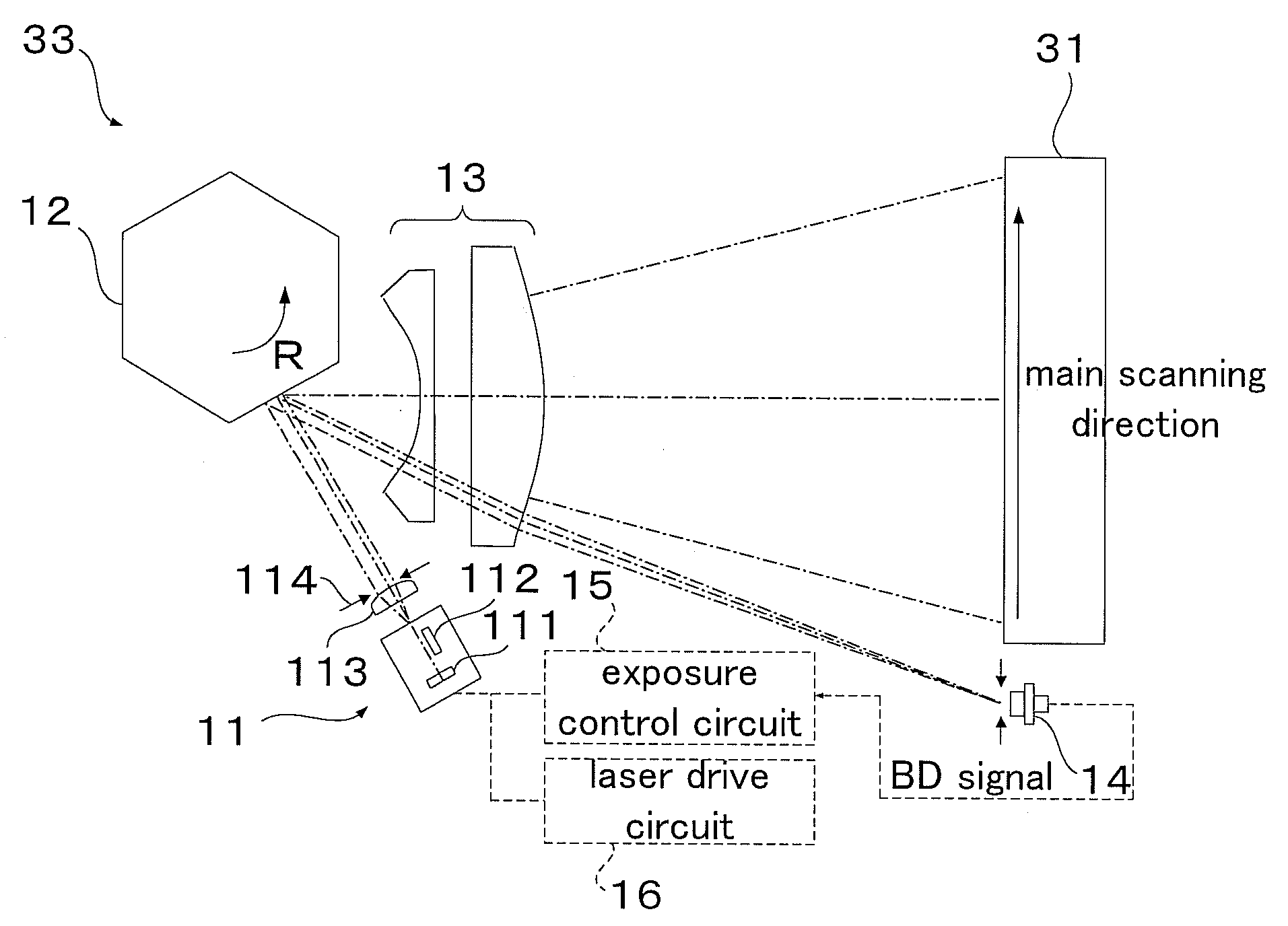
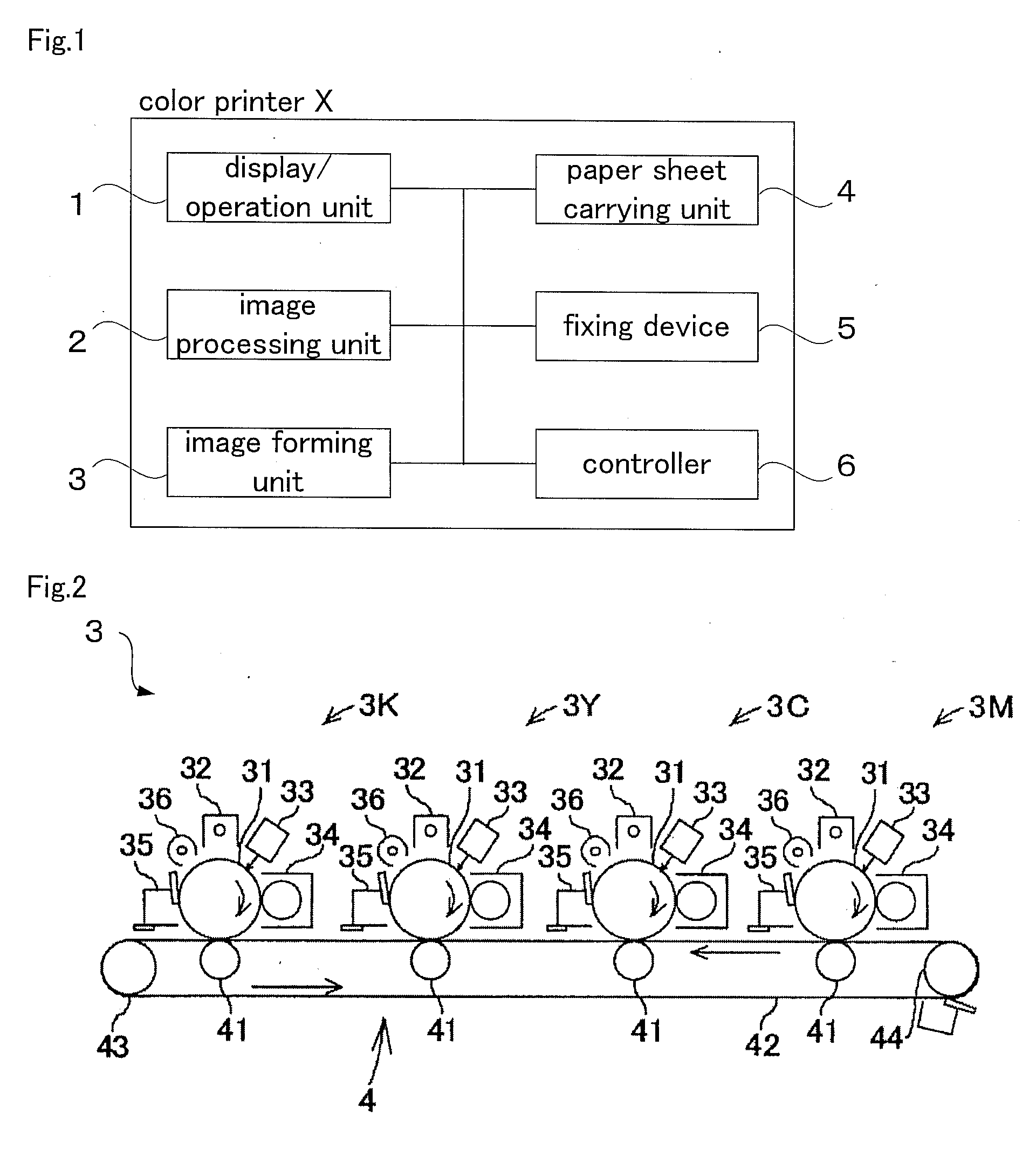
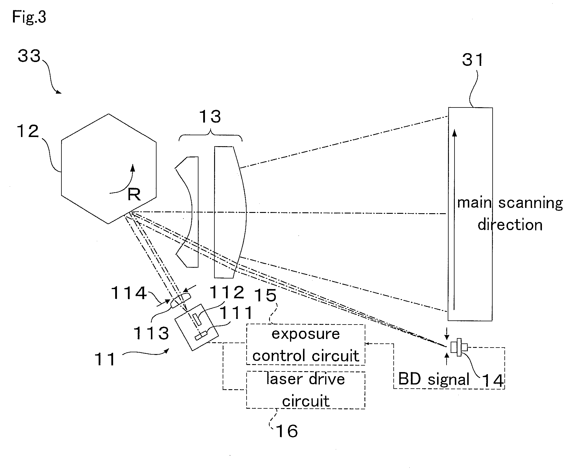
[0034]Here, FIG. 1 is a block diagram showing a general configuration of a color printer X according to one embodiment of the present invention; FIG. 2 is a schematic configuration diagram of an image forming unit 3 in the color printer X; FIG. 3 is a pattern diagram showing a general configuration of an optical scanner 33 provided in the image forming unit 3; FIG. 4 is a timing chart for explaining exposure processing in every line by the optical scanner 33; FIG. 5 is a circuit diagram of a laser sensor 14, and FIG. 6 shows one example of operation characteristics of the laser sensor 14.

[0035]In addition, the color printer X according to the present embod


PUM


Abstract

The emission intensity of a laser beam source, at a time when a laser beam emitted from the laser beam source and scanned by an optical scanning device becomes incident to a laser beam detector provided in a predetermined position on the scanning path of the laser beam in order to hold a position of an electrostatic latent image formed on a photoreceptor constant in the main scanning direction, while at the same time, changing the emission intensity of the laser beam, is set so as to become the consistently same emission intensity regardless of a change in emission intensity at the time of electrostatic latent image formation onto a photoreceptor. This allows the detection timing of a laser beam by a laser beam detector to be kept constant.

Description


Claims


Application Information

Patent Timeline
Owner KYOCERA DOCUMENT SOLUTIONS INC
Why Eureka
Try Eureka