Composition and Manufacturing Method

Active Publication Date: 2011-07-07
GENERAL ELECTRIC CO
View PDF5 Cites 17 Cited by
  • Summary
  • Abstract
  • Description
  • Claims
  • Application Information

AI Technical Summary

Problems solved by technology

Mechanical devices for numerous applications including provision of circuit breakers and high voltage, high current switching have been large in size and often require large forces to activate the switching mechanism.
Such conventional switches also operate at relatively slow speeds.
They are often complex and expensive to fabricate.
Energy associated with the arc may degrade the switch contacts or present a hazardous situation.
Since solid-state switches do not provide a physical gap between contacts when they

Method used


Image

  • Composition and Manufacturing Method
  • Composition and Manufacturing Method
  • Composition and Manufacturing Method

Examples


Embodiment Construction

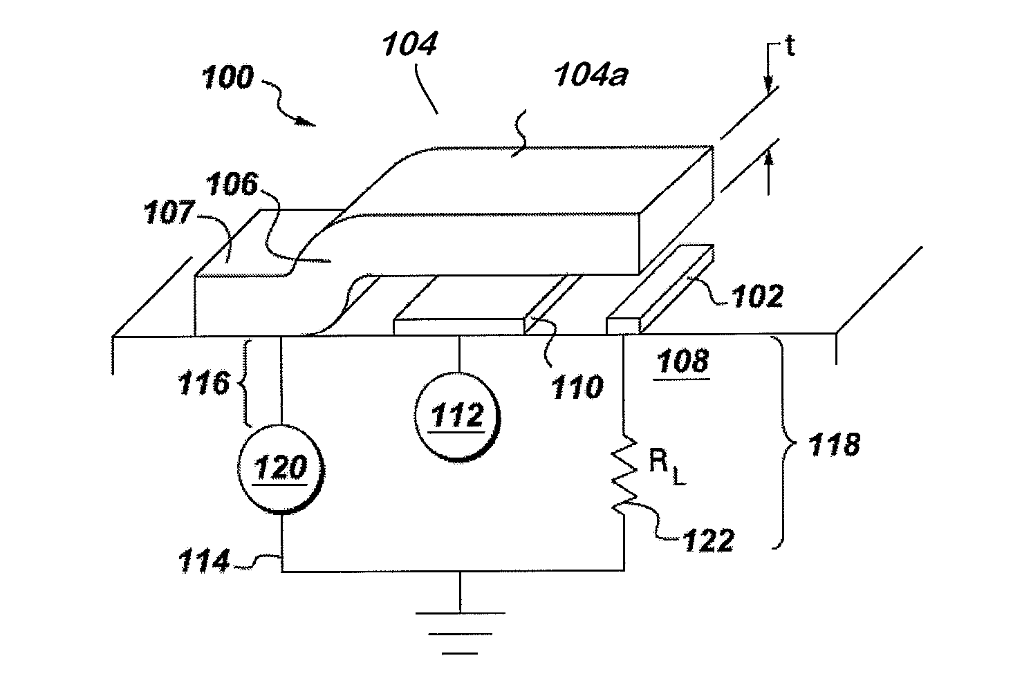
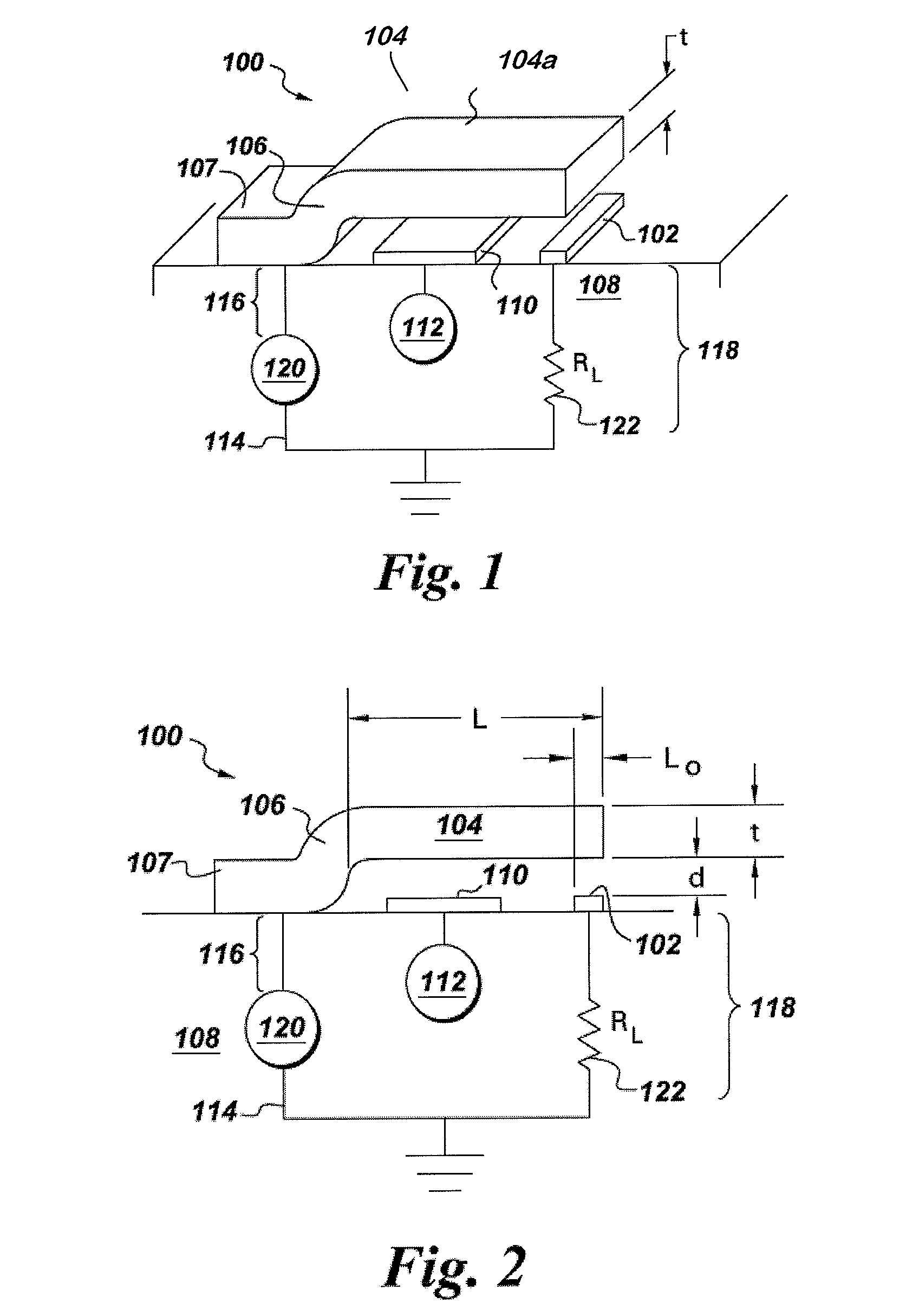
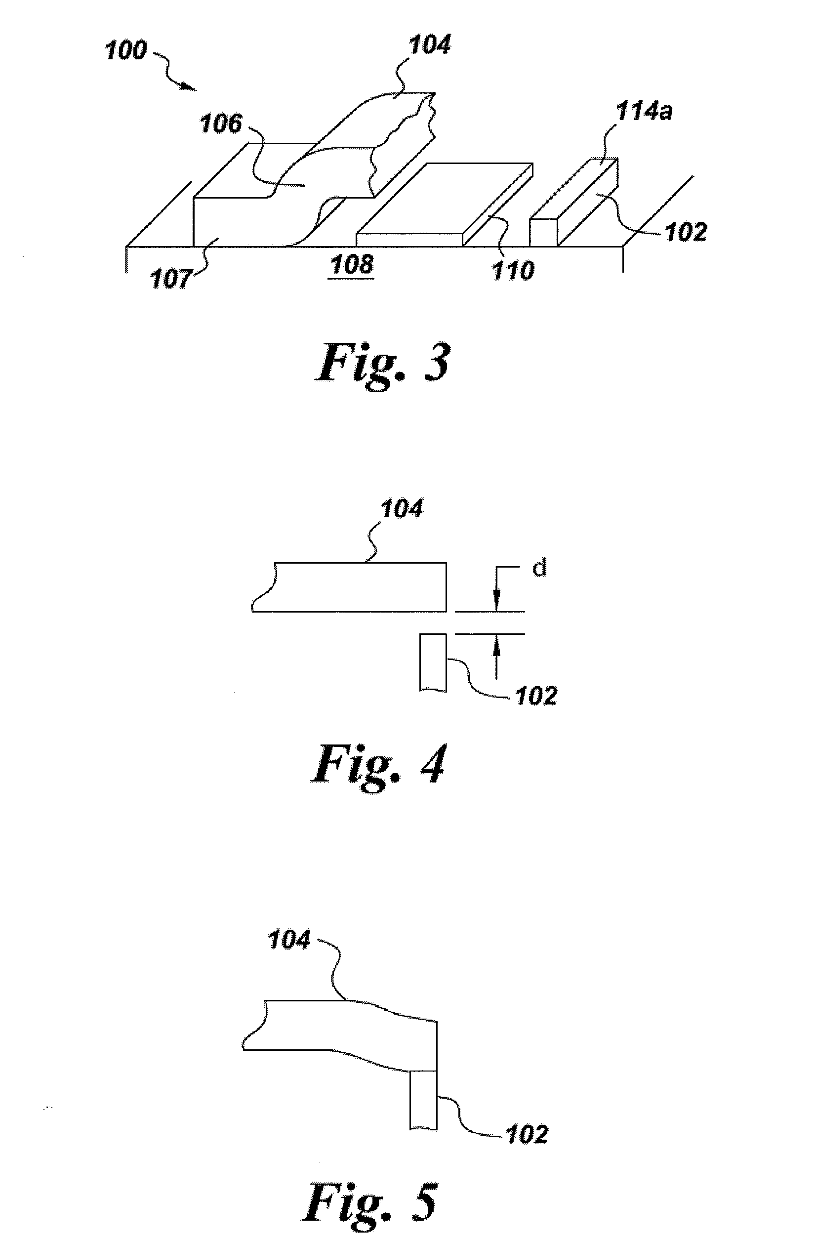
[0031]Example embodiments are now described with reference to the accompanying drawings. Some of these embodiments may address the above and other needs. Referring to FIGS. 1-3, several views are shown of a switch structure 100 configured in accordance with an example embodiment. The example switch structure 100 includes a contact 102, which at least partially comprises a conductive material (e.g., a metal). The switch structure 100 also includes a conductive element, illustrated as a cantilevered beam 104, comprising conductive material (e.g., a metal). A cantilevered portion 104a of the beam extends over the contact 102. In some embodiments, the conductive element may also include other features, such as, for example, a protective (and possibly non-conductive) coating on the beam 104 or a contact pad disposed along the portion of the beam intended to make contact with the contact 102. The beam 104 can be supported by an anchor 106 and a base 107, from which the cantilevered portion 1


PUM

PropertyMeasurementUnit
Temperatureaaaaaaaaaa
Fractionaaaaaaaaaa
Timeaaaaaaaaaa

Abstract

A device includes a substrate (308) and a metallic layer (336) formed over the substrate (308) with a deposition process for which the metallic layer (336) is characterizable as having a pre-determinable as-deposited defect density. As a result of a fabrication process, the defect density of the metallic layer (336) is reduced relative to the pre-determinable as-deposited defect density of the same layer (336) or another layer having like composition and which is formed under like deposition conditions. In a related method, a substrate (308) is provided and a removable layer (330) is formed over the substrate (308). A metallic layer (336) is formed over the removable layer (330) and is patterned and etched to define a structure over the removable layer (330). The removable layer (330) is removed, and the metallic layer (336) is heated for a time beyond that necessary for bonding of a hermetic sealing cap (340) thereover.

Description


Claims


Application Information

Patent Timeline
Owner GENERAL ELECTRIC CO
Why Eureka
Try Eureka