Electric cable shield structure

Active Publication Date: 2011-12-01
OKINO KENTARO +1
View PDF3 Cites 3 Cited by
  • Summary
  • Abstract
  • Description
  • Claims
  • Application Information

AI Technical Summary

Benefits of technology

[0008]As described above, according to the present invention, the electric cable structure which is able to cut-off the effect of the external noises as low as the limit thereof may be provided.

Problems solved by technology

When the electric cable receives such external noises, the signals under communication may be disturbed and erroneous actions may take place in a precise electronic apparatus such as a computer in the worst case.
Such metal sheets could provide certain shield effects for the electro-magnetic wave; however, it has been insufficient with respect to a vibration absorption effect.
Moreover, when the shield layer of the audio cable is constructed by using a copper sheet or an aluminum sheet, the technical problem that incongruity on timbre of the output sounds (i.e., so called overlap of metallic sounds) has been caused because resonance components being unique to the above metal materials are migrated to the sound signals.

Method used


Image

  • Electric cable shield structure
  • Electric cable shield structure
  • Electric cable shield structure

Examples


Example

EXAMPLE

[0040]Hereafter, the present invention will be detailed more concretely using practical examples; however, the present invention must not be limited to the examples described hereafter.

Example

Example 1

—Examination of Shield Effect of Magnesium Shield—

[0041]To evaluate the shield effect of the magnesium shield of the present invention, several experiments were conducted. The evaluation examinations described hereunder were conducted by using Absorption Clamp Test specified in IEC SPECIFICATION (IEC1196-1, IEC61196-1).

[0042]Commercially available LAN cable (category 6, total length 7 m, available from SANWA SUPPLY INC., Type Number KB-T7E-07) was used as the electric cable.

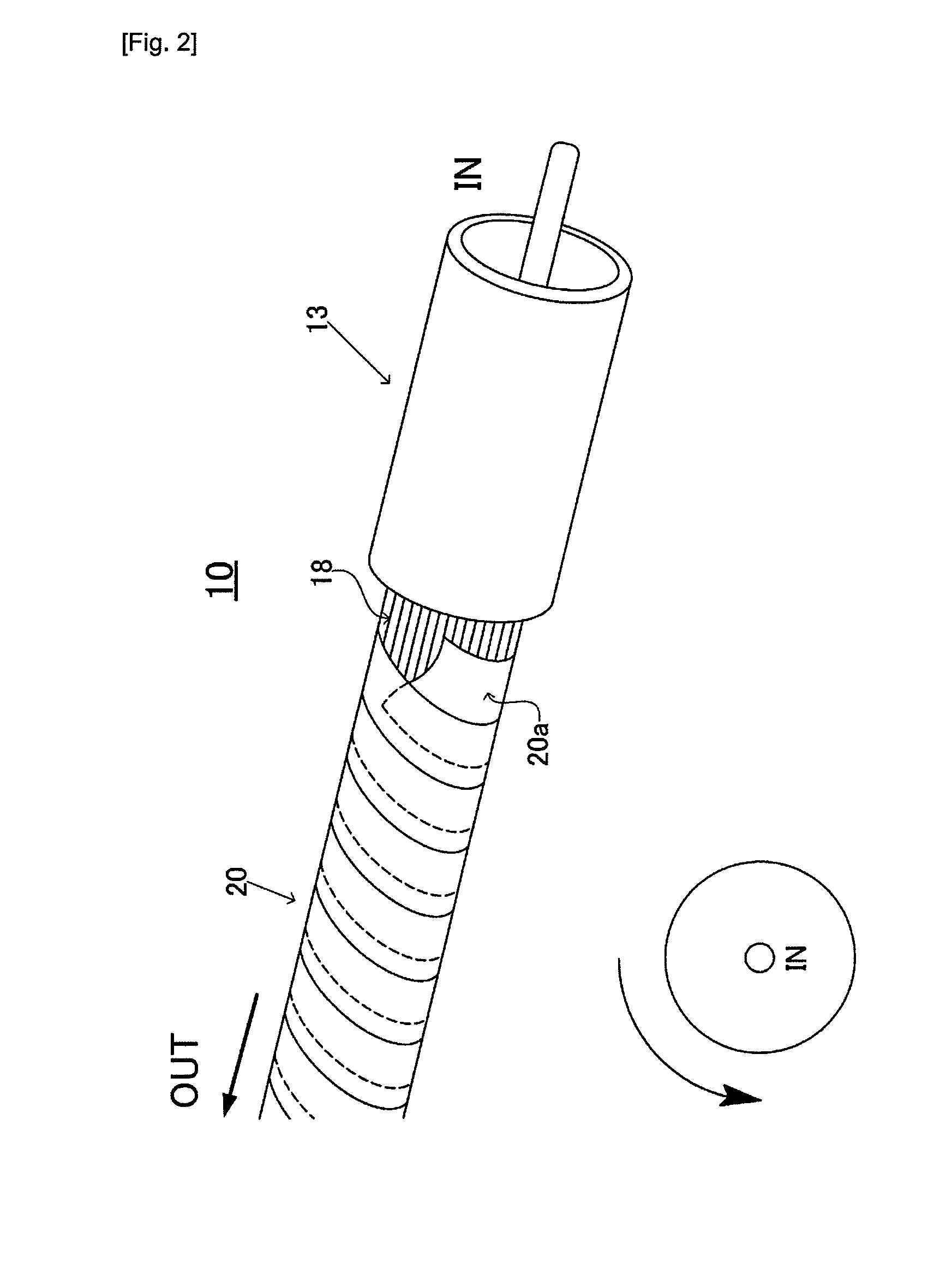
[0043]An aluminum alloy tape (width 20 mm, thickness 45 micro-meters, magnesium content percentage 95-96%, Aluminum 3%, Zinc 1%, Product Serial Number AZ31B, available from NIPPON KINZOKU CO., LTD.) was wound spirally to the above LAN cable such that the spiral was developed to be counter clock wise when viewed from the IN end. The tape winding was performed by evenly overlapping about one half of the tape width each other with starting from the IN end and finishing the OUT end direction so as not to remain

Example

Example 2

[0048]—Examination of Effect on Sounds by Magnesium Shield—

[0049]A sense of hearing test was conducted by connecting audio apparatuses with the cables implemented with the magnesium shield structure of the present invention.

[0050]—Preparation of Magnesium Shield Cable—

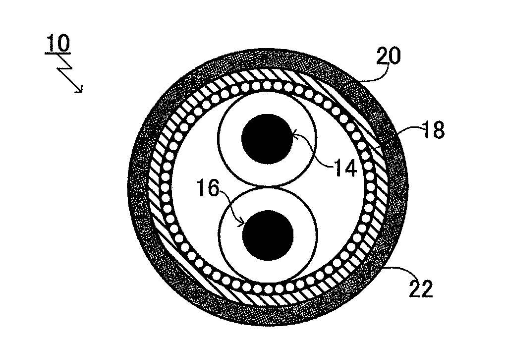
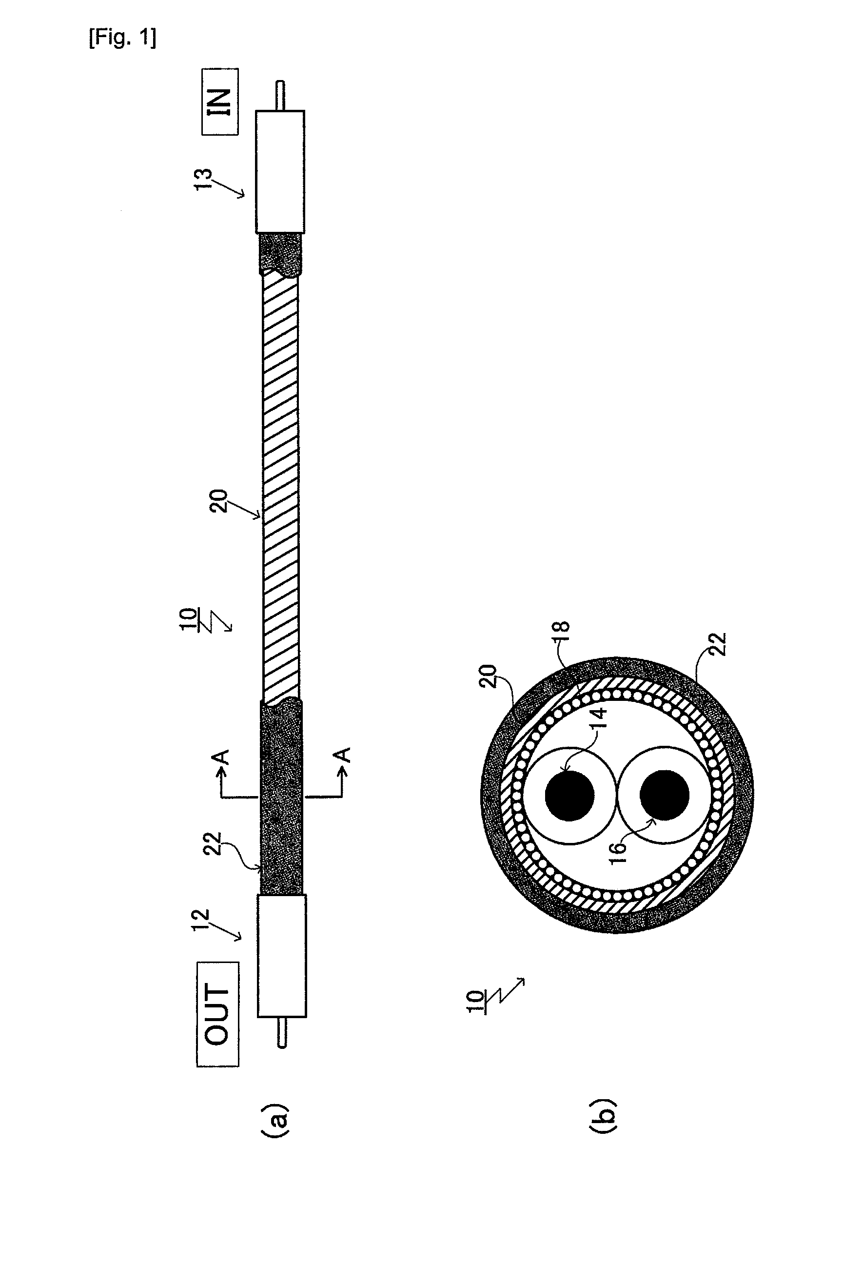
[0051]The magnesium shield cable of the present embodiment was prepared by using a conventional audio cable. FIGS. 6(a)-(c) shows a preparation steps of the magnesium shield cable as the time sequence of the production process and in each of the figures, the side view and the cross sectional view (along with A-A line) of each processes are depicted. Hereafter, the formation of the magnesium shield cable will be described with referencing FIG. 6.

[0052]As shown in FIG. 6(a), first of all, the audio cable commercially available was selected. The audio cable 30 was a popular and commercially available RCA cable (Product Number K-1, available from KRYNA PRO CO., Total length 1000 mm) which was shielded by the copper b


PUM

PropertyMeasurementUnit
Fractionaaaaaaaaaa
Electrical conductivityaaaaaaaaaa
Structureaaaaaaaaaa

Abstract

The present invention relates to a novel shield structure for an electric cable which is able to cut-off the effect of the external noises as low as the limit thereof.
A metal sheet tape including magnesium as a major component thereof having high electro-magnetic shield performance, high vibration absorption performance as well as high heat conductivity being wound spirally on an outer circumference of the electric cable may provide a high performance shield layer. Furthermore in an AV cable, original sounds may be recovered with extremely high faithfulness by forming a shield layer with winding spirally the metal sheet tape, which includes magnesium as a major component and is wound in the counter clockwise direction in the direction viewed from an IN end to an OUT end of an AV cable.

Description


Claims


Application Information

Patent Timeline
Owner OKINO KENTARO
Why Eureka
Try Eureka