Method and apparatus for the formation of solar cells with selective emitters

Inactive Publication Date: 2013-04-18
APPLIED MATERIALS ITALIA SRL
View PDF0 Cites 2 Cited by
  • Summary
  • Abstract
  • Description
  • Claims
  • Application Information

AI Technical Summary

Benefits of technology

[0022]Wavelengths longer than 14 μm are generally more advantageous, but the range between about 8 μm and 14 μm provides an acceptable compromise between costs of the now commercially available long-wa

Problems solved by technology

The high market growth rate in combination with the need to substantially reduce solar electricity costs has resulted in a number of serious challenges for inexpensively forming high quality solar cells.
The misalignment of the deposited fingers 14 to the underlying heavily doped regions 17 due to errors in the positioning of the substrate on an automated transferring device, defects in the edge of the substrate, unknown registration and alignment of the heavily doped region

Method used


Image

  • Method and apparatus for the formation of solar cells with selective emitters
  • Method and apparatus for the formation of solar cells with selective emitters
  • Method and apparatus for the formation of solar cells with selective emitters

Examples


first embodiment

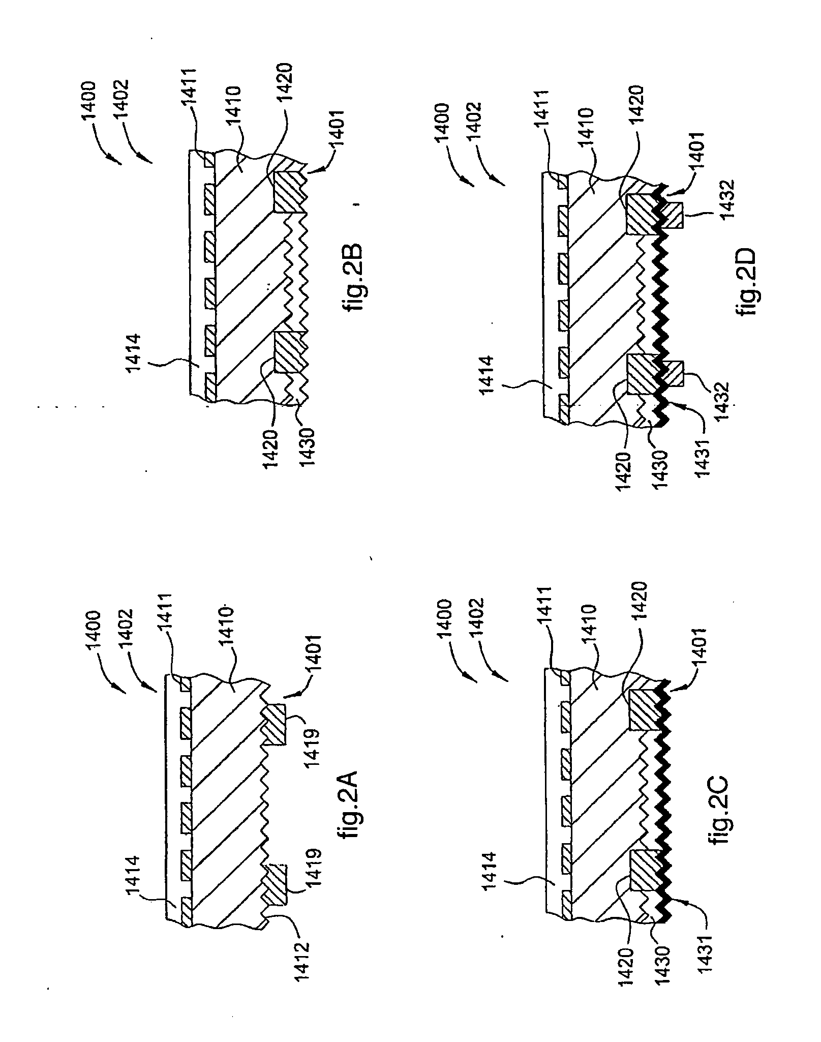
[0131]In a first embodiment, the acquisition of the pattern of the first heavily doped regions 1420 at step 704 provides operation in the field of visible light, adopting an optical filter, and using the optical inspection system 400 and a technique of processing the images acquired by the system 400, based on Fourier transform, while using the control system 101.

[0132]The first embodiment uses the optical inspection system 400, in which the electromagnetic radiation emitted by the radiation source 403 and received by the detector assembly 401, for example by the camera 401A (FIG. 4B), is in the visible wavelength of between about 400 nm and about 900 nm. It has been found that this first embodiment works well in the case of strong contrasts between the SE lines defined by the first heavily doped regions 1420 and the substrate, particularly in the second doped emitter region 1430, due to differences in the texture or steps of different heights. However, if there is a weak natural contr

second embodiment

[0139]The second embodiment according to the invention can be actuated in two variants.

[0140]A first variant of the second embodiment provides controlling the substrate 1410 optically with the detector assembly 401 while it is at a temperature above ambient temperature, even by only a few degrees Celsius (° C.) (FIG. 10). In one embodiment, the range of wavelengths is longer than, or equal to, about 8 μm. In another embodiment the range is between about 8 μm and 14 μm. In the above described ranges, it is possible, unlike in the detection in the visible or short waves of infrared, to use the contrast mechanism represented by the difference in heat emissivity between the SE lines defined by the first heavily doped regions 1420 and the substrate, in particular the second doped emitter region 1430, since at a given temperature the two regions emit different quantities of infrared light. The first variant has the advantage that it does not require any illumination by means of the radiation


PUM


Abstract

Methods and apparatus for forming solar cells with selective emitters are provided. A method includes positioning a substrate on a substrate receiving surface. The substrate has a surface comprising a first patterned heavily doped region having a first dopant concentration that defines the selective emitters, and a second doped emitter region having a second dopant concentration that is less than the first dopant concentration, wherein the second doped emitter region surrounds the first patterned heavily doped region. The method further comprises determining a position of the first patterned heavily doped region by using a Fourier transform to process a filtered optical image, aligning one or more distinctive elements in a screen printing mask with the first patterned heavily doped region by using information received from the determined position of the first patterned heavily doped region, and depositing a layer of material on a portion of the first patterned heavily doped region.

Description


Claims


Application Information

Patent Timeline
Owner APPLIED MATERIALS ITALIA SRL
Why Eureka
Try Eureka