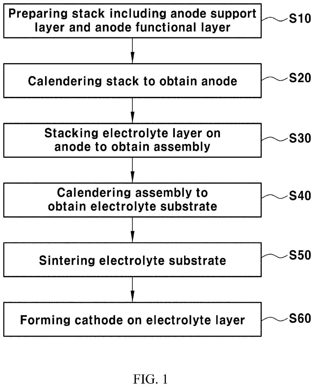
Method of manufacturing solid oxide fuel cell including multi-layered electrolyte layer using calendering process
a solid oxide fuel cell and multi-layer electrolyte technology, which is applied in the manufacture of cell components, final product products, electrochemical generators, etc., can solve the problems of increasing the price of sofc system components, accelerating device deterioration, and single cell fabricated through the above process, so as to achieve the effect of improving densification
- Summary
- Abstract
- Description
- Claims
- Application Information
AI Technical Summary
Benefits of technology
Problems solved by technology
Method used
Image

Examples
preparation example 1
Support Layer
[0100]Nickel oxide (NiO), yttria-stabilized zirconia (YSZ) and polymethylmethacrylate (PMMA) were mixed at a volume ratio of 28:42:30 to obtain a powder. The powder and a solvent were mixed at a volume ratio of 24:76 to obtain a slurry. In this case, a mixed solvent containing ethanol and toluene was used as the solvent.
[0101]2.3 parts by weight of a polyester / polyamine condensation polymer (Hypermer KD-1, ICI chemical Co., Spain) as a dispersant, 9.3 parts by weight of poly(vinyl butyral) (PVB) as a binder, and 9.3 parts by weight of dibutyl phthalate as a plasticizer were added to 100 parts by weight of the slurry. The slurry was ball-milled for about 24 hours and then aged for about 24 hours.
[0102]The slurry was tape-cast to obtain an anode support layer sheet.
preparation example 2
Functional Layer
[0103]Nickel oxide (NiO) and yttria-stabilized zirconia (YSZ) were mixed at a volume ratio of 40:60 to obtain a powder. The powder and a solvent were mixed at a volume ratio of 24:76 to obtain a slurry. In this case, a mixed solvent containing ethanol and toluene was used as the solvent.
[0104]2.47 parts by weight of a polyester / polyamine condensation polymer (“Hypermer” KD-1) as a dispersant, 9.2 parts by weight of poly(vinyl butyral) (PVB) as a binder, and 8.49 parts by weight of dibutyl phthalate as a plasticizer were added to 100 parts by weight of the slurry. The slurry was ball-milled for about 24 hours and then aged for about 24 hours.
[0105]The slurry was tape-cast to obtain an anode functional layer sheet.
preparation example 3
Electrolyte Layer
[0106]An Fe-yttria-stabilized zirconia (Fe-YSZ) powder coated on the surface of 2 mol % of iron (Fe) based on 100 mol % of the total of the first electrolyte layer (Fe-YSZ electrolyte) and a solvent were mixed at a volume ratio of 7:93 to obtain a slurry. A mixed solvent containing ethanol and toluene was used as the solvent.
[0107]2.5 parts by weight of a polyester / polyamine condensation polymer (“Hypermer” KD-6) as a dispersant, 8.5 parts by weight of poly(vinyl butyral) (PVB) as a binder, and 10.5 parts by weight of dibutyl phthalate as a plasticizer were added to 100 parts by weight of the slurry. The slurry was ball-milled for about 24 hours and then aged for about 24 hours.
[0108]The slurry was tape-cast to obtain a first electrolyte layer sheet (Fe-YSZ electrolyte).
PUM
 Abstract
Description
Claims
Application Information
 - R&D Engineer
- R&D Manager
- IP Professional
- Industry Leading Data Capabilities
- Powerful AI technology
- Patent DNA Extraction
Browse by: Latest US Patents, China's latest patents, Technical Efficacy Thesaurus, Application Domain, Technology Topic.
© 2024 PatSnap. All rights reserved.Legal|Privacy policy|Modern Slavery Act Transparency Statement|Sitemap