Image processing device, method, image reading device, and recording medium
- Summary
- Abstract
- Description
- Claims
- Application Information
AI Technical Summary
Benefits of technology
Problems solved by technology
Method used
Image

Examples
first embodiment
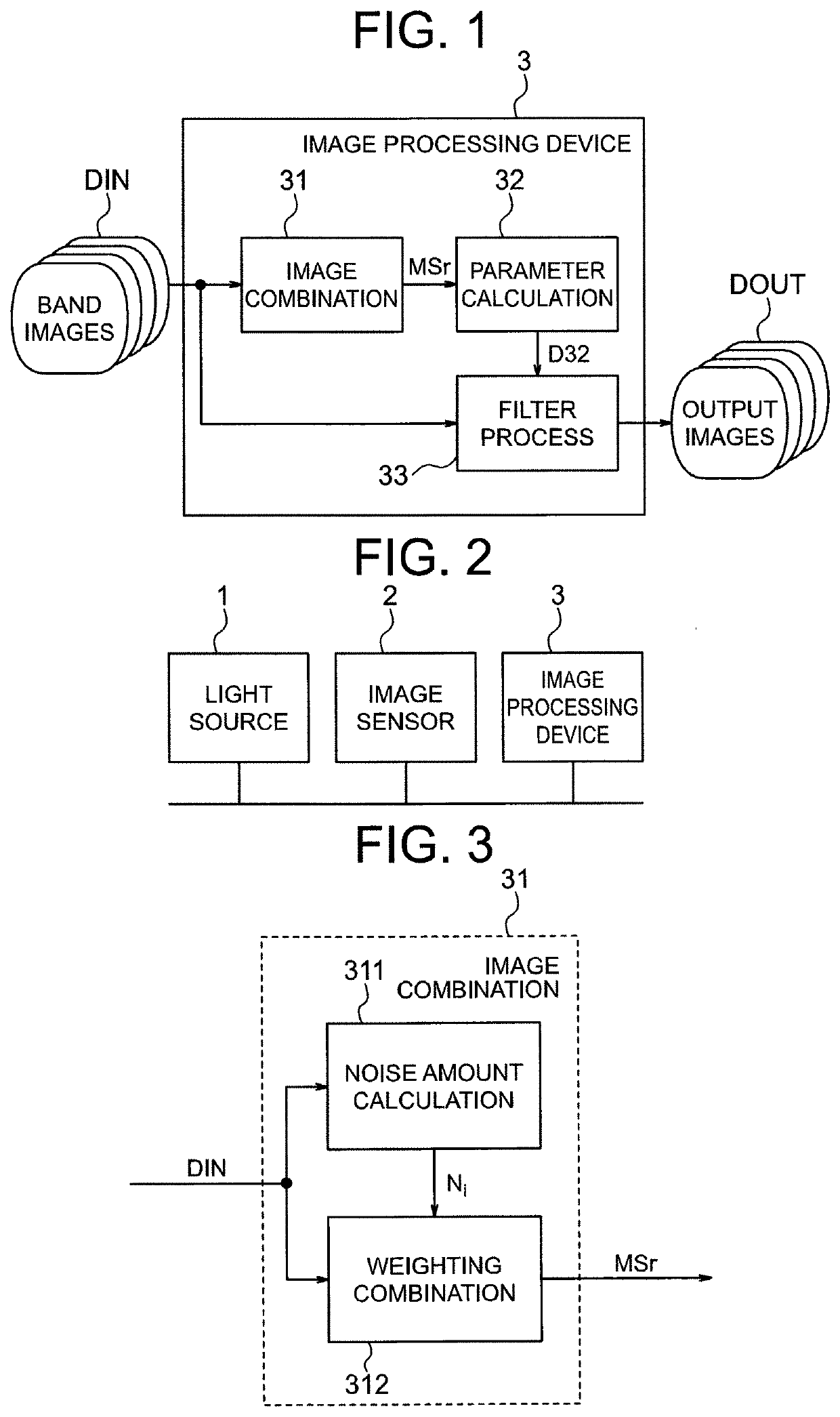
[0026]FIG. 1 is a block diagram illustrating an image processing device 3 of a first embodiment of the present invention. FIG. 2 illustrates a configuration example of an image reading device including the image processing device 3 of FIG. 1.
[0027]The image reading device illustrated in FIG. 2 includes a light source 1 and an image sensor 2, in addition to the image processing device 3.
[0028]The light source 1 is constituted by multiple light sources each having a relatively narrow band. Hereinafter, the light sources having the relatively narrow bands will be referred to as band light sources. The multiple band light sources include, for example, a light source having a visible light wavelength band, a light source having an ultraviolet wavelength band, and a light source having a near-infrared wavelength band. The multiple band light sources are controlled to sequentially illuminate an original one by one.
[0029]The image sensor 2 sequentially obtains multiple band images DIN by imagi
second embodiment
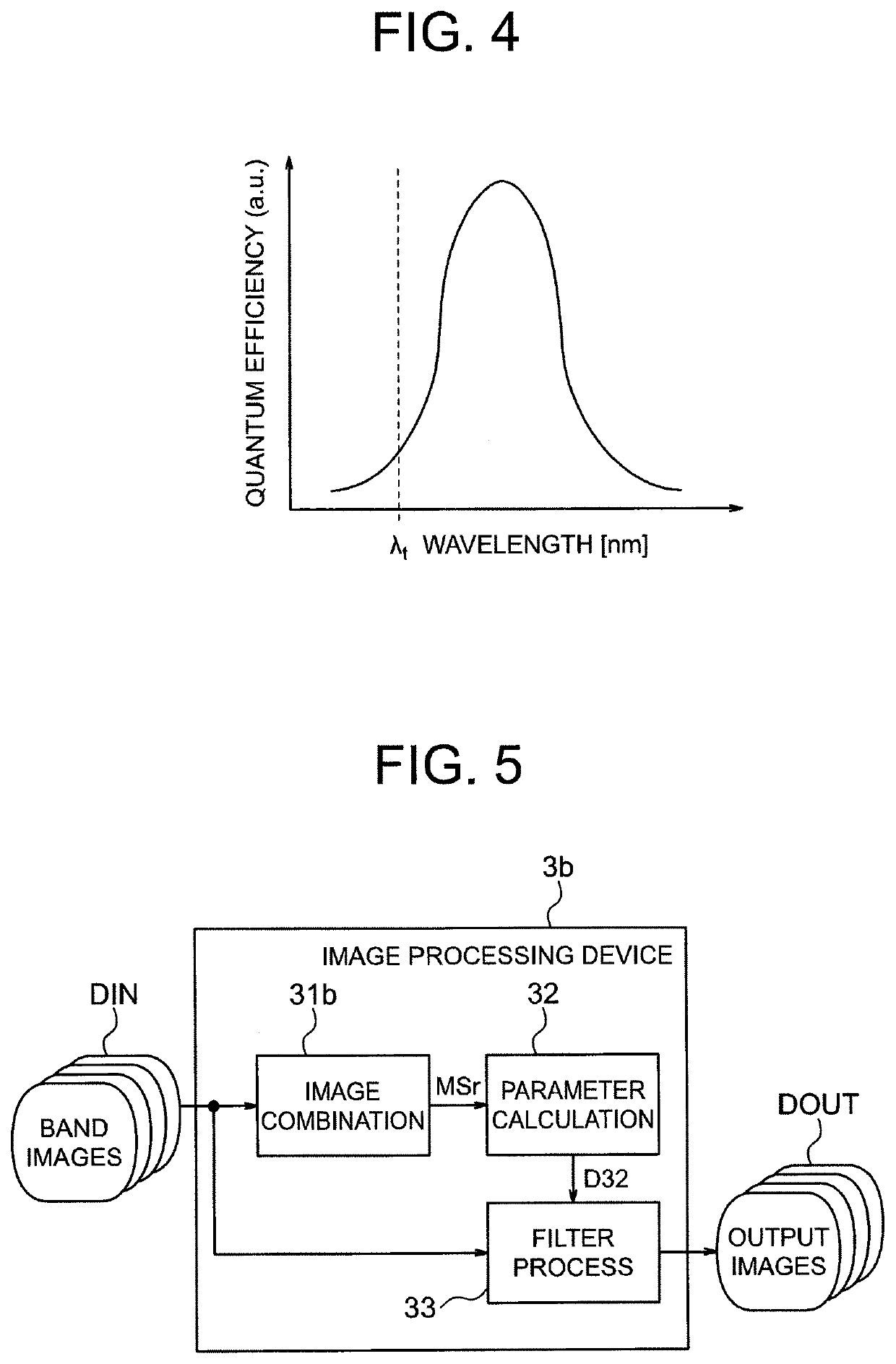
[0094]FIG. 5 illustrates an image processing device 3b of a second embodiment of the present invention.
[0095]The illustrated image processing device 3b is generally the same as the image processing device 3 of FIG. 1, but includes an image combiner 31b instead of the image combiner 31.
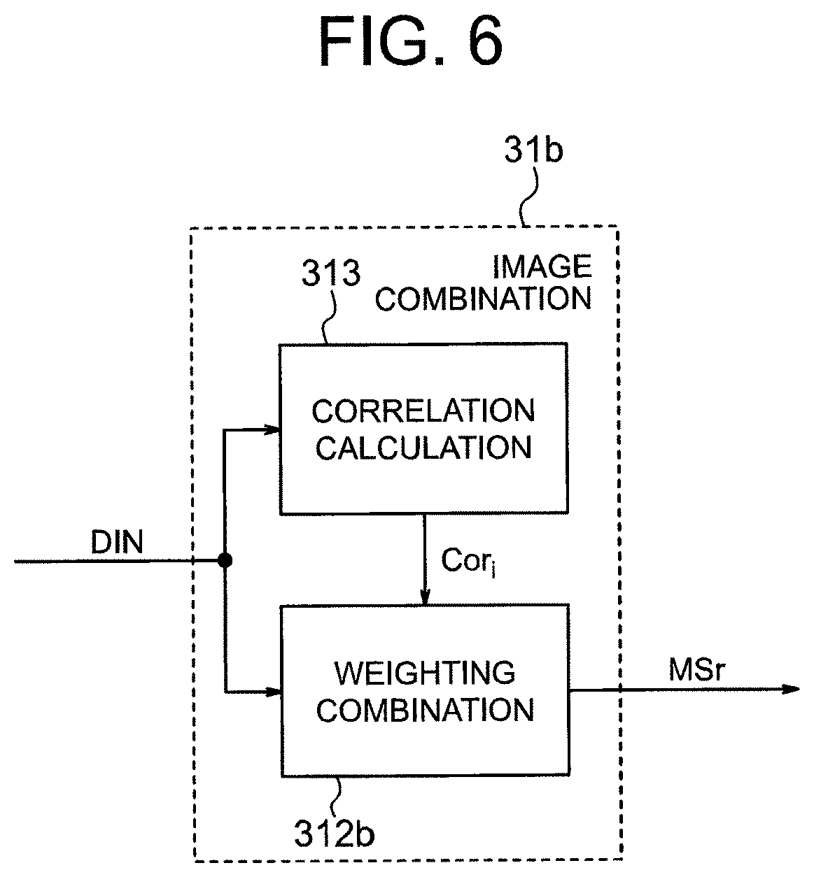
[0096]The image combiner 31 of the first embodiment performs the image combination such that the combination weight of a band image whose noise amount is greater is smaller. The image combiner 31b of this embodiment performs the image combination by using combination weights determined on the basis of image correlations between the band images.
[0097]The image characteristics of each band image depend on its wavelength band, and the farther the wavelength bands of two band images are from each other, the greater the difference in image characteristics between the two band images.
[0098]In this embodiment, when it is intended to reduce the noise of a band image of a certain wavelength band, the reference ima
third embodiment
[0133]FIG. 8 illustrates an image processing device 3c of a third embodiment of the present invention.
[0134]The illustrated image processing device 3c is generally the same as the image processing device 3 of FIG. 1, but does not include the image combiner 31 of FIG. 1 and includes a parameter calculator 32c instead of the parameter calculator 32 of FIG. 1.
[0135]Also, in addition to the band images DIN of FIG. 1, a white image DIW is input to the image processing device 3c.
[0136]The band images DIN are the same as the band images of FIG. 1.
[0137]The white image DIW is an image having a band including all the bands of the multiple band images DIN, and is used as a reference image. The band of the white image DIW is preferably wider than a band obtained by summing all the bands of the multiple band images DIN.
[0138]The parameter calculator 32c analyzes the white image DIW, and for each pixel of the white image DIW, calculates a local variance or an edge amount as an image feature amount
PUM
 Abstract
Description
Claims
Application Information
 - R&D Engineer
- R&D Manager
- IP Professional
- Industry Leading Data Capabilities
- Powerful AI technology
- Patent DNA Extraction
Browse by: Latest US Patents, China's latest patents, Technical Efficacy Thesaurus, Application Domain, Technology Topic.
© 2024 PatSnap. All rights reserved.Legal|Privacy policy|Modern Slavery Act Transparency Statement|Sitemap