Polymer powder storage and/or transport and/or degassing vessels

a technology of polymer powder and storage tank, which is applied in the direction of antibody medical ingredients, chemical/physical/physico-chemical processes, chemistry apparatus and processes, etc., can solve the problems of regular powder flowability of applications, and achieve the effect of high production ra

Active Publication Date: 2013-07-30
INEOS SALES (UK) LTD
View PDF5 Cites 2 Cited by
  • Summary
  • Abstract
  • Description
  • Claims
  • Application Information

AI Technical Summary

Benefits of technology

This patented technology allows for efficient use of equipment when producing polyethylene plastics that can have sizes greater than three thousand kilograms or even larger. It also improves productivity compared to traditional methods like batch processing techniques such as extrusion moldings.

Problems solved by technology

This patented technical problem addressed during this patents relates to improving the performance or efficiency of existing solutions for storing and delivering bulk materials like plastic pellets (PPE) without causing trouble due to poor fluidity caused by accumulation on bags containing them.

Method used


Image

  • Polymer powder storage and/or transport and/or degassing vessels
  • Polymer powder storage and/or transport and/or degassing vessels
  • Polymer powder storage and/or transport and/or degassing vessels

Examples


Embodiment Construction

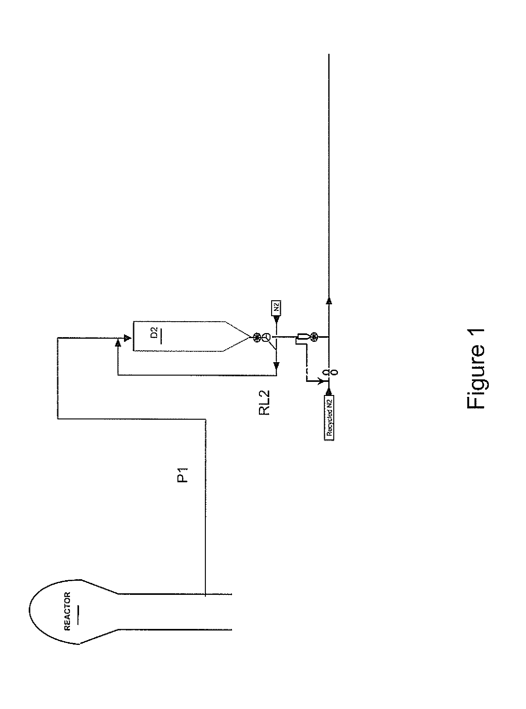
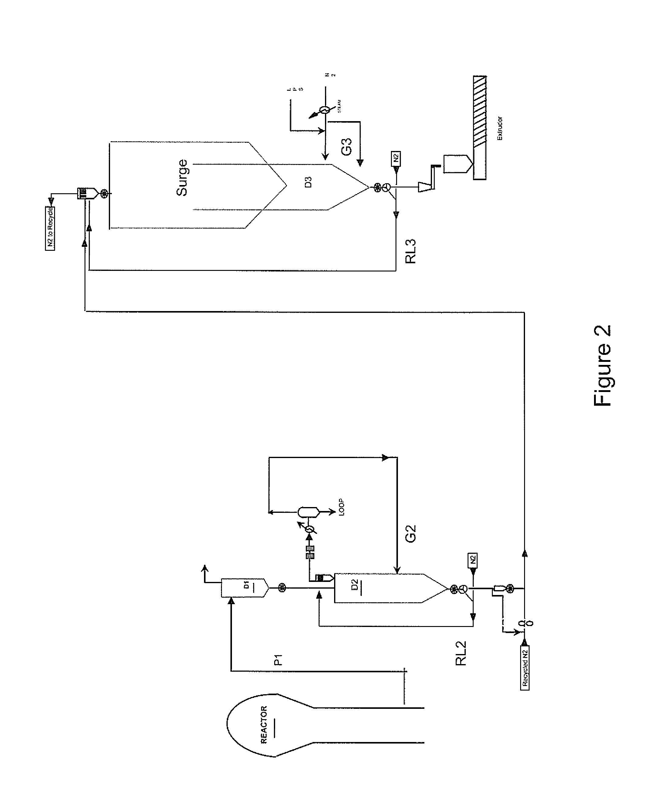
[0083]In its broadest aspect, an embodiment of the present invention is described in FIG. 1 or FIG. 2 wherein the polymer powder degasser vessel (D2 or D3)—comprising the polymer powder recirculation line (which can be RL2 or RL3)—is located downstream of the polymerization reactor and upstream of the polymer powder extruder wherein said powder is transformed into pellets.

[0084]In FIG. 1, the polymer powder P1 which is withdrawn from the fluidised bed gas phase polymerisation reactor is entered into the polymer powder degasser vessel D2.

[0085]In another embodiment, which is described in FIG. 2, the degassing line comprises two polymer powder degasser vessels in series (D2 and D3), both of which comprising their respective polymer powder recirculation line (RL2, RL3).

[0086]It will also be apparent from the FIG. 2 that RL3 represents a specific recirculation embodiment of the present invention wherein two silos (the polisher silo D3 and the surge silo) are used in series; indeed, the rei


PUM

PropertyMeasurementUnit
Percent by massaaaaaaaaaa
Volumeaaaaaaaaaa

Abstract

Polymer powder vessel having a silo including a main vertical cylinder and a hopper at the bottom of the cylinder, a polymer powder which occupies the full volume of the hopper and at least a part of the volume of the cylinder, a polymer powder silo inlet pipe connected to the silo at a height located above the polymer powder, and a polymer hopper withdrawal pipe is also connected to the hopper. The polymer powder hopper withdrawal pipe is also connected to the silo at a location above the polymer powder for recirculating a part of the polymer powder within the silo.

Description


Claims


Application Information

Patent Timeline
Owner INEOS SALES (UK) LTD
Why Eureka
Try Eureka