Low-friction sliding material and low-friction pressurizing member for toner fixing devices
A technology of sliding parts and pressurized parts, applied in the direction of anti-centrifugal rotating parts, sliding contact bearings, additives, etc.
- Summary
- Abstract
- Description
- Claims
- Application Information
AI Technical Summary
Benefits of technology
Problems solved by technology
Method used
Image
Examples
Embodiment 1)
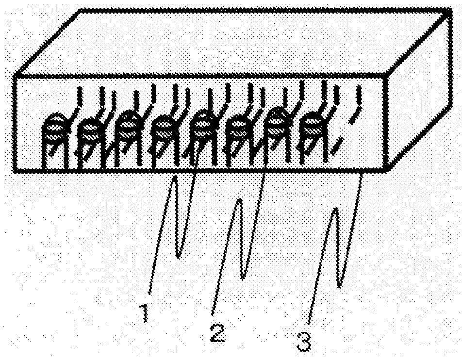
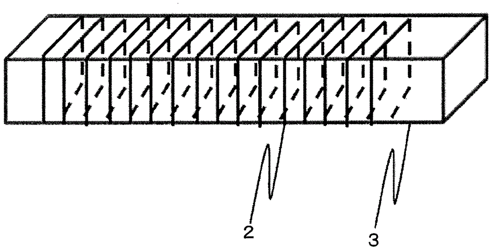
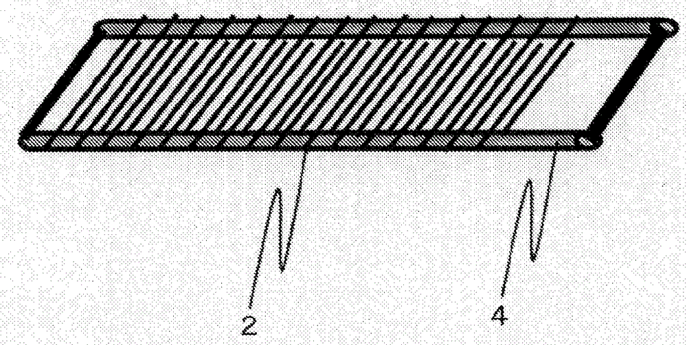
[0080] As the fluorine-containing fiber, a PTFE fiber of 440 dtex, 60 filaments, and a twist number of 300 t / m was used, and it was wound on a sliding part to produce a sliding part model. For the sliding member, a 235×80×3 mm SUS304 stainless steel plate was used for the measurement of the dynamic friction coefficient, and a 30×30×2 mm polyacetal resin plate was used for the ring wear test.
[0081] The winding takes place by means of hand winding in such a way that the wound fibers do not overlap each other and no gaps occur. Adjacent fibers are juxtaposed in the same direction. The fiber coverage of the test body for measuring the coefficient of dynamic friction and the ring wear test body was 100%.
Embodiment 2)
[0083] As the conjugated fiber including fluorine-containing fibers, a PTFE fiber of 440 dtex, 60 filaments, and a twist number of 300 t / m and a PPS fiber of 220 dtex, 50 filaments, and a twist number of 300 t / m were used. The weight ratio of the fluorine-containing fiber at this time was 67%.
[0084] The PPS fiber selected as another fiber to be combined with the fluorine-containing fiber has a higher tensile strength and a lower creep rate than the PTFE fiber. That is, it is as follows.
[0085] PTFE fiber: tensile strength 616cN, creep rate 4.5%
[0086] PPS fiber: tensile strength 924cN, creep rate 2.0%
[0087] In addition, here, the tensile strength is defined as the tensile strength by measuring the breaking strength according to JIS L1013:2010 (chemical fiber filament test method). The creep rate is fixed at one end of the fiber under the standard state (20°C×65%RH), and the tension acting on the fiber at the other end is suspended at a load of 20% of the breaking
Embodiment 3)
[0091] It was the same as in Example 2 except that the gaps between the wound fibers were substantially evenly spaced when winding the fibers, and the number of turns to the test body was reduced to about 90% of that of Example 2. Adjacent fibers are juxtaposed in the same direction. The fiber coverage at this time was 89% for the test pieces for measuring the coefficient of dynamic friction, and 90% for the ring wear test pieces.
PUM
 Abstract
Description
Claims
Application Information
 - R&D Engineer
- R&D Manager
- IP Professional
- Industry Leading Data Capabilities
- Powerful AI technology
- Patent DNA Extraction
Browse by: Latest US Patents, China's latest patents, Technical Efficacy Thesaurus, Application Domain, Technology Topic.
© 2024 PatSnap. All rights reserved.Legal|Privacy policy|Modern Slavery Act Transparency Statement|Sitemap


