Directional reconfigurable microelectromechanical antenna and preparation method thereof

A micro-electro-mechanical and directional technology, applied to antennas, microstructure devices composed of deformable elements, antenna components, etc., can solve the problems that cannot meet beamforming and fast scanning, and achieve light weight and process Fully Compatible, Low Power Effects

Active Publication Date: 2017-03-22
NANJING UNIV OF POSTS & TELECOMM
View PDF4 Cites 5 Cited by
  • Summary
  • Abstract
  • Description
  • Claims
  • Application Information

AI Technical Summary

Problems solved by technology

[0003] In order to achieve the above goals well, the classic single-mode antenna can no longer meet the requirements of the radar syste

Method used


Image

  • Directional reconfigurable microelectromechanical antenna and preparation method thereof
  • Directional reconfigurable microelectromechanical antenna and preparation method thereof
  • Directional reconfigurable microelectromechanical antenna and preparation method thereof

Examples


Embodiment Construction

[0037] Below in conjunction with accompanying drawing, technical scheme of the present invention is described in further detail:

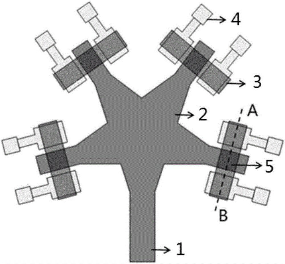
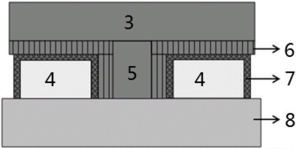
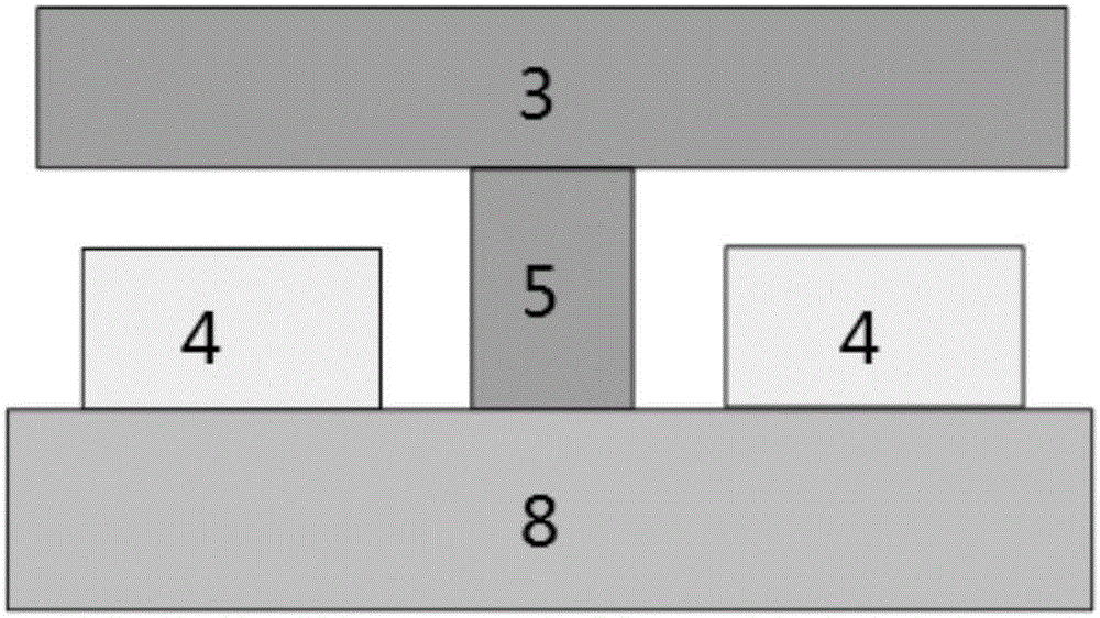
[0038] The directional reconfigurable microelectromechanical antenna of the present invention is a directional reconfigurable microwave antenna, with GaAs as the substrate, such as Figures 1 to 3 As shown, the microelectromechanical antenna uses gallium arsenide as a substrate 8, and on the substrate are provided a microstrip antenna feeder 1, a star-shaped structure microstrip antenna radiation element 2, a MEMS cantilever beam 3, a cantilever beam bridge pier 5, a cantilever Beam pull-down electrode 4, SiN dielectric layer 7 and polyimide sacrificial layer 6.

[0039] Any four radiation ends of the star-shaped microstrip antenna radiating element 2 are respectively connected to a cantilever beam pier 5, each cantilever beam pier 5 is connected to a MEMS cantilever beam 3, and the bottom of each MEMS cantilever beam 3 is on the cantilever beam A ca


PUM

PropertyMeasurementUnit
Thicknessaaaaaaaaaa
Thicknessaaaaaaaaaa
Thicknessaaaaaaaaaa

Abstract

The invention discloses a directional reconfigurable microelectromechanical antenna and a preparation method thereof. According to the microelectromechanical antenna, gallium arsenide is taken as a substrate, and the substrate is provided with a microstrip antenna feeder, a star-like structure microstrip antenna radiation element, an MEMS cantilever beam and a cantilever beam pier. The MEMS cantilever beam is bent at different degrees through applying voltage with the same polarity and different magnitudes to pull-down electrodes at the same side of the cantilever beam, thereby achieving small directional reconfiguration on the microwave antenna. Two sides of the MEMS cantilever beam are bent in opposite directions through applying the voltage with opposite polarities to pull-down electrodes at the left side and the right side of the cantilever beam, thereby achieving large directional reconfiguration on the microwave antenna.

Description


Claims


Application Information

Patent Timeline
Owner NANJING UNIV OF POSTS & TELECOMM
Why Eureka
Try Eureka