Double shaft furnace system and method for joint production

A combined production and shaft furnace technology, applied in the field of metallurgy, can solve problems such as reducing the comprehensive utilization rate of reducing gas, increasing the requirements for preparing reducing gas, and energy utilization, so as to improve energy utilization, reduce equipment complexity, and improve production. effect of ability

Pending Publication Date: 2017-12-26
JIANGSU PROVINCE METALLURGICAL DESIGN INST
View PDF0 Cites 4 Cited by
  • Summary
  • Abstract
  • Description
  • Claims
  • Application Information

AI Technical Summary

Benefits of technology

This patented technology allows for an improved process called Shell Oil Gas (SOG), where both high purity gases like oxygen or nitrogen are produced from separate sources at once. By optimally coupling these reactants with specific reactor settings, this new process achieves higher efficiency than existing processes without sacrificing productivity levels. Additionally, the combination of catalyst systems helps create multiple types of chemical compounds such as ammonia, formaldehydes, acids, etc., resulting in various benefits including lower greenhouse gas emissions during manufacturing operations, enhanced reductions in power consumption, and simplified equipment designs. Overall, this innovation enables integrated coal-fired electric generation into long term storage and economic growth opportunities through synergies between fuel combustion and reduction gas usage rates.

Problems solved by technology

Technological Problem: Current methods involve decompositing greenhouse gases (CO2) emitted through combustion processes such as coal burning power plants. These techniques can lead to environmental pollution due to their harmful effects on human health caused by nitrogen oxides produced when fossil fuels burned together. To address this issue, various proposes aim at developing new ways to recover these valuable metal elements while minimizing carbon dioxide emission associated with traditional sources like coking operations.

Method used


Image

  • Double shaft furnace system and method for joint production
  • Double shaft furnace system and method for joint production

Examples


Embodiment 1

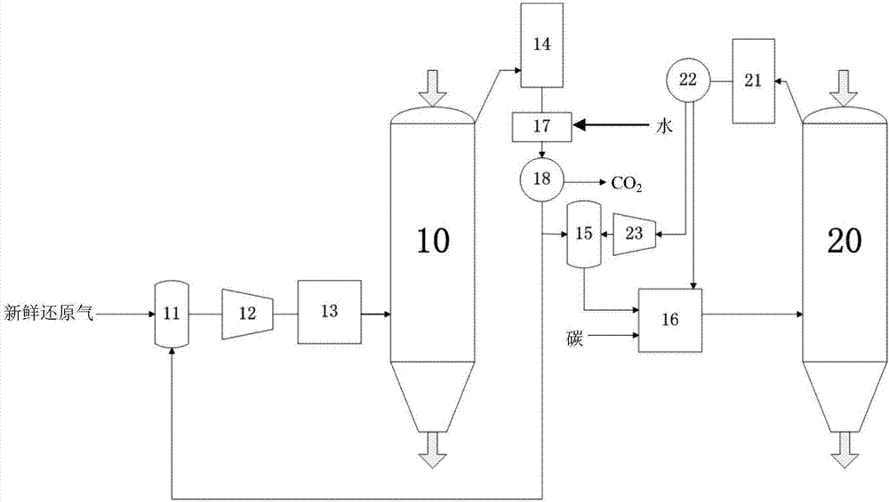
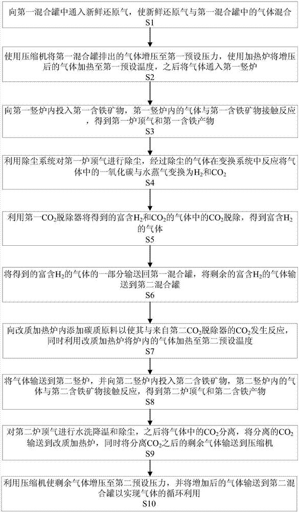
[0072] Vanadium-titanium-magnetite pellets are put into the first shaft furnace 10 , and iron concentrate pellets are put into the second shaft furnace 20 . Fresh reducing gas and hydrogen-rich gas are mixed in the first mixing tank 11 to make the mixed gas composition reach H 2 With a volume ratio of 5 to CO, the effective reducing gas (H 2 +CO) volume ratio higher than 0.95. The mixed gas is passed into the first compressor 12 to make the pressure of the mixed gas reach 0.8MPa, and then passed into the heating furnace 13 for heating, so that the temperature reaches 1100°C. The heated mixed gas passes into the first shaft furnace 10 and reacts in the first shaft furnace 10 to generate vanadium-titanium sponge iron and the first top gas. The first furnace top gas pressure is 0.7MPa. Through the dry dust removal system 14, the conversion system 17 and the first CO 2 The hydrogen-rich gas is obtained after treatment by the remover 18 . Send part of the hydrogen-rich gas back t

Embodiment 2

[0076] Vanadium-titanium-magnetite pellets are put into the first shaft furnace 10 , and iron concentrate pellets are put into the second shaft furnace 20 . Fresh reducing gas and hydrogen-rich gas are mixed in the first mixing tank 11 to make the mixed gas composition reach H 2 With a volume ratio of 5 to CO, the effective reducing gas (H 2 +CO) volume ratio higher than 0.90. The mixed gas is passed into the first compressor 12 to make the pressure of the mixed gas reach 0.7 MPa, and then passed into the heating furnace 13 for heating so that the temperature thereof reaches 1050°C. The heated mixed gas passes into the first shaft furnace 10 and reacts in the first shaft furnace 10 to generate vanadium-titanium sponge iron and the first top gas. The first furnace top gas pressure is 0.65MPa. Through the dry dust removal system 14, the conversion system 17 and the first CO 2 The hydrogen-rich gas is obtained after treatment by the remover 18 . Send part of the hydrogen-rich g

Embodiment 3

[0080] Vanadium-titanium-magnetite pellets are put into the first shaft furnace 10 , and iron concentrate pellets are put into the second shaft furnace 20 . Fresh reducing gas and hydrogen-rich gas are mixed in the first mixing tank 11 to make the mixed gas composition reach H 2 With a volume ratio of 4 to CO, the effective reducing gas (H 2 +CO) volume ratio higher than 0.95. The mixed gas is passed into the first compressor 12 to make the pressure of the mixed gas reach 0.4MPa, and then passed into the heating furnace 13 for heating, so that the temperature reaches 1000°C. The heated mixed gas passes into the first shaft furnace 10 and reacts in the first shaft furnace 10 to generate vanadium-titanium sponge iron and the first top gas. The first furnace top gas pressure is 0.3MPa. Through the dry dust removal system 14, the conversion system 17 and the first CO 2 The hydrogen-rich gas is obtained after treatment by the remover 18 . Send part of the hydrogen-rich gas back t


PUM


Abstract

The invention discloses a double shaft furnace system and method for joint production. The double shaft furnace system comprises a first mixing tank, a first compressor, a heating furnace, a first shaft furnace, a dust removal system, a conversion system, a first CO2 remover, a second mixing tank, a modified heating furnace, a second shaft furnace, a water washing tower, a second CO2 remover, a second compressor and connecting pipelines between all the above components. The invention further discloses a method for jointly producing iron-containing products by using the system. According to the system and the method, the two shaft furnaces with different working conditions are combined based on the different characteristics of a vanadium titano-magnetite mineral resource and an iron ore concentrate resource so as to realize direct reduction of different minerals; different pressures of reaction conditions of the two shaft furnaces are utilized, so that the gradient use of the pressure is effectively realized, the energy utilization rate is improved, the equipment investment cost is reduced to a certain extent, and the equipment complexity is reduced; and the characteristic that the volume ratio of hydrogen to carbon monoxide in effective reducing gas in the first shaft furnace is different from the volume ratio of hydrogen to carbon monoxide in effective reducing gas in the second shaft furnace is effectively utilized, so that efficient utilization of energy and resources is realized.

Description


Claims


Application Information

Patent Timeline
Owner JIANGSU PROVINCE METALLURGICAL DESIGN INST
Why Eureka
Try Eureka