Internal self-cleaning pipelined skylight system
A pipeline-type, self-cleaning technology, applied in roof cladding, gas treatment, construction, etc., can solve the problems of inability to solve the problem of air purification of light pipes, inability to perform air purification, and inability to control the passage of ultraviolet rays.
- Summary
- Abstract
- Description
- Claims
- Application Information
AI Technical Summary
Problems solved by technology
Method used
Image

Examples
Embodiment 1
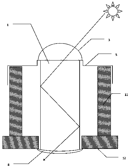
[0041] like Figure 4 Shown in, the structure and working principle of the present invention are as follows. The present invention includes: dual-frequency light guide tube 2, light collector 3, ultraviolet light cover 4, rainproof buckle plate 5, invisible light leakage window 6, photocatalyst coating 7, diffuser 8, ultraviolet light shield 9, leakage window cover Sheet 13. In the present embodiment, the profile of the dual-frequency light pipe 2 is a columnar body, a cylinder, or a square column; the rainproof pinch plate 5 is provided with a rainproof pinch plate central hole 14 and an ultraviolet opening 31, The rainproof gusset 5 is a planar shape and the central hole 14 of the rainproof gusset is located at its central part; the ultraviolet light cover 4 is a light-transmitting body with a thickness, specifically a light-transmitting body for ultraviolet rays to pass through; The ultraviolet light cover 4 is arranged on the position except the rainproof pinch plate centra
Embodiment 2
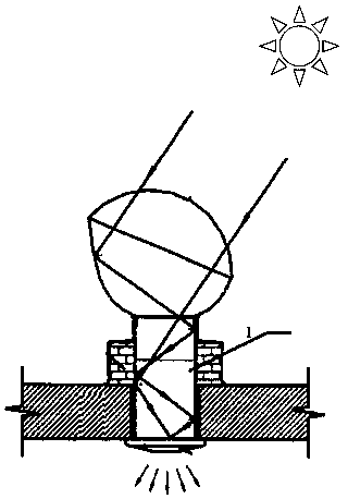
[0060] Figure 10 The structure and working principle of Embodiment 2 are shown, and the overall structure is similar to Embodiment 1. like Figure 10 As shown in , there are two main differences between embodiment 2 and embodiment 1, namely: first, the shape of the dual-frequency light pipe 2 includes a partial horizontal platform 17, and the horizontal platform is located above the building structure well 11; the second Two, the position of the invisible light leakage window 6 is changed from being placed vertically on the dual-frequency light pipe 2 to being placed horizontally on the horizontal platform 17 . The working principle of embodiment 2 is: light beam one 15 (containing the ultraviolet frequency band) irradiates on the ultraviolet mask 4, and penetrates the ultraviolet mask 4 and enters the internal space jointly formed by the building structure well 11 and the rainproof gusset 5; Then the light beam one 15 continues to advance and enters the dual-frequency light p
Embodiment 3
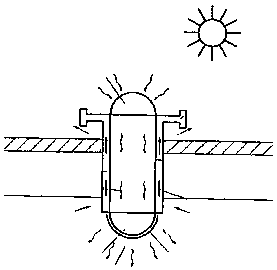
[0062] Figure 11 The structure of Example 3 is shown, and the overall structure is similar to that of Example 1. like Figure 11 As shown in , the main difference between Embodiment 3 and Embodiment 1 is that a plurality of ultraviolet generators 10 that emit electromagnetic waves upward are installed on the diffuser 8 . The ultraviolet generator 10 is configured to generate ultraviolet light only when the ultraviolet light shield 9 is in the position of completely shielding the ultraviolet light mask 4 . The purpose of installing the ultraviolet generator 10 is to add extra ultraviolet radiation dose to the space formed by the dual-frequency light guide pipe 2 and the building structure well 11 under the following two situations, so as to enhance the work of exciting the photocatalyst 7 and sterilize and purify the air The role of: one, when long-term cloudy days cause insufficient ultraviolet radiation to enter the system through the ultraviolet light mask 4 in natural light
PUM
 Abstract
Description
Claims
Application Information
 - R&D Engineer
- R&D Manager
- IP Professional
- Industry Leading Data Capabilities
- Powerful AI technology
- Patent DNA Extraction
Browse by: Latest US Patents, China's latest patents, Technical Efficacy Thesaurus, Application Domain, Technology Topic.
© 2024 PatSnap. All rights reserved.Legal|Privacy policy|Modern Slavery Act Transparency Statement|Sitemap