Reshaping station for blow molding machines without pressure pads

A molding station and blow molding technology, applied in the field of molding stations, can solve the problems of high cost, high cost, high expenditure, etc., and achieve the effect of avoiding rapid wear and tear

Active Publication Date: 2018-12-21
KRONES AG
View PDF3 Cites 0 Cited by
  • Summary
  • Abstract
  • Description
  • Claims
  • Application Information

AI Technical Summary

Problems solved by technology

However, relatively high costs are incurred due to the need for pressure pads to achieve a flush and positive engagement of the blow mold, e.g. for supplying compressed air to the pressure pads
Tubing and p

Method used


Image

  • Reshaping station for blow molding machines without pressure pads
  • Reshaping station for blow molding machines without pressure pads
  • Reshaping station for blow molding machines without pressure pads

Examples


Embodiment Construction

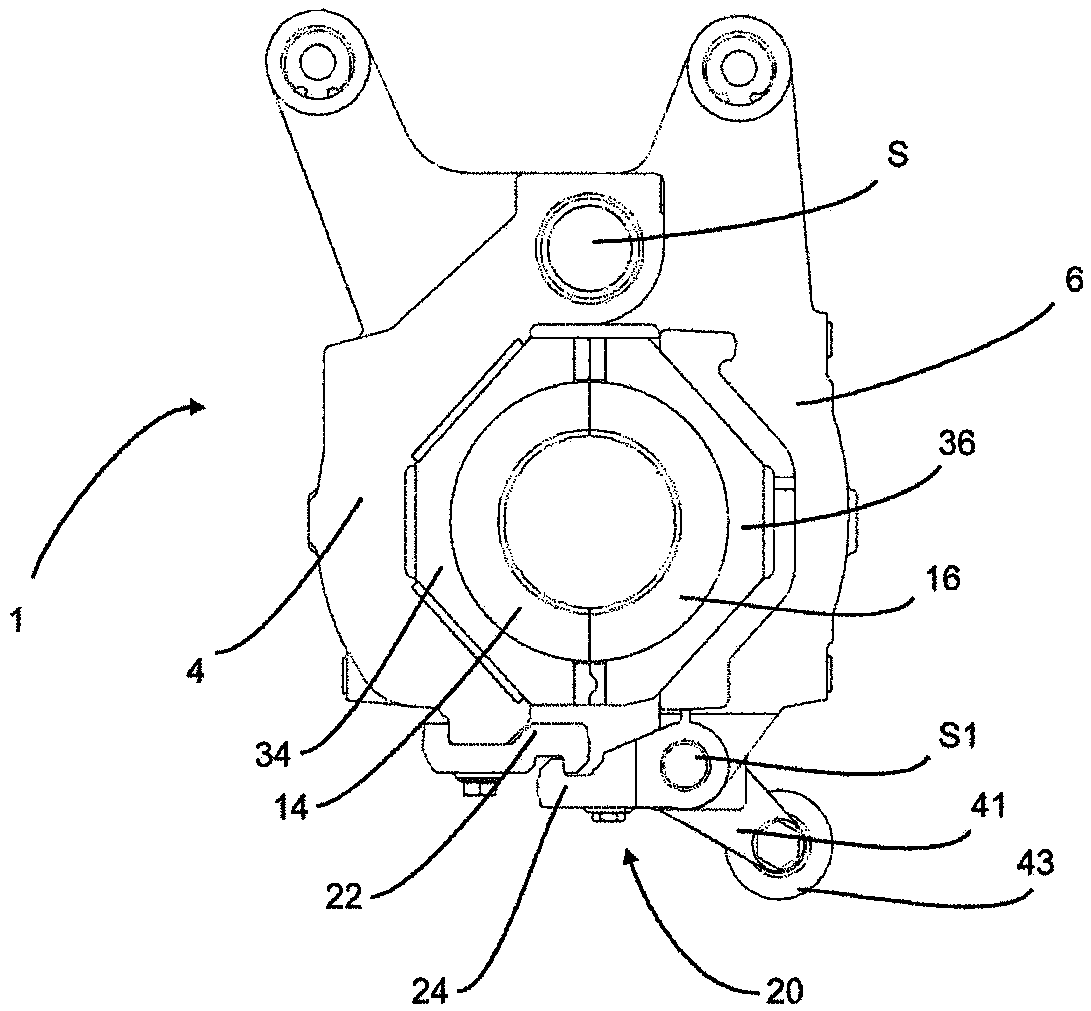
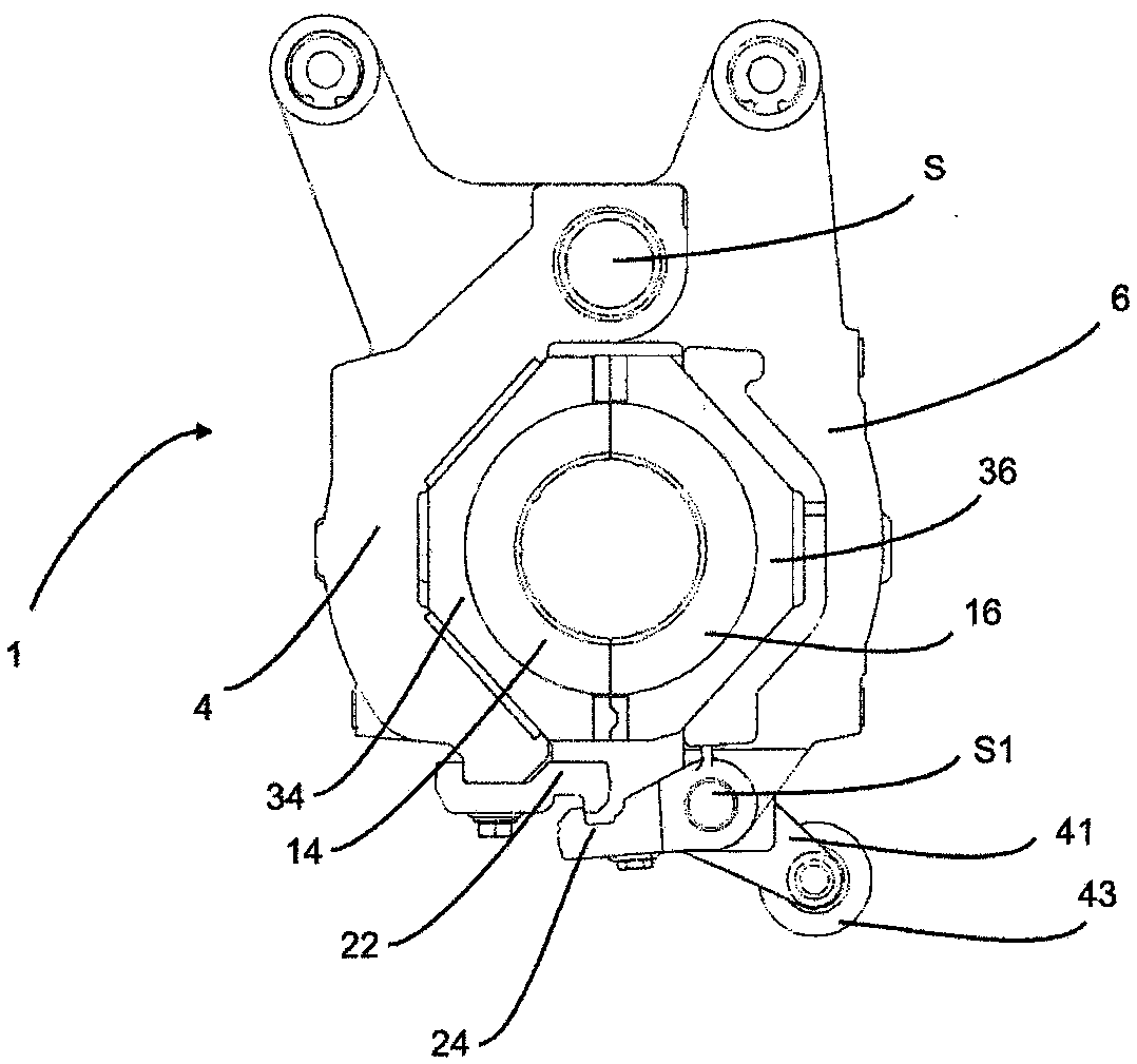
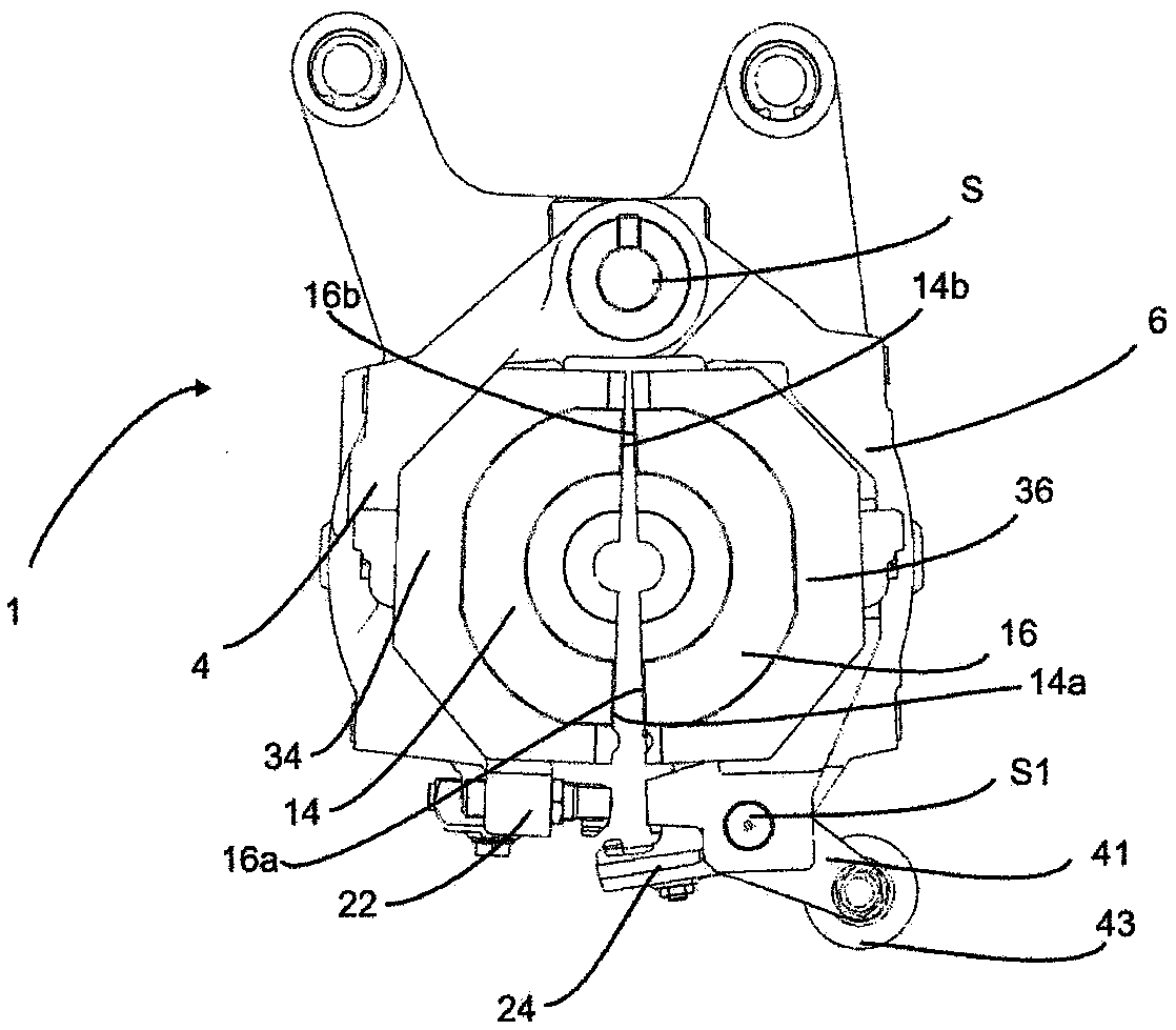
[0051] exist figure 1 A forming station 1 according to the invention is shown in . The forming station 1 has two side supports 4 and 6 . They are rotatable about the main axis S relative to each other. In this case, both side supports may rotate about this main axis. It is also possible that only one of the two side supports rotates about the main axis. It is also conceivable to provide two axes parallel to each other about which the two side supports rotate. Here, the main axis S or the corresponding rotational axis runs perpendicular to the drawing plane. The mold shells 34 and 36 are each arranged on two blow mold supports. The blow mold sides 14 and 16 are arranged successively on these mold shells 34 and 36 .


PUM


Abstract

The invention relates to a reshaping station (1) for reshaping plastic preforms (10) into plastic containers. The reshaping station (1) has two lateral part supports (4, 6) for supporting lateral parts (14, 16) of a blow mold and preferably a base part support for supporting a base part of the blow mold. The lateral parts (14, 16) and the base part (18) of the blow mold together form a cavity (15)within which the plastic preforms (10) can be reshaped into the plastic containers by applying a flowable medium. At least one of the two lateral part supports can be pivoted relative to the other lateral part support with respect to a specified main axis (S) in order to open and/or close the blow mold, and the reshaping station has a locking mechanism in order to lock one lateral part support (4) with the other lateral part support (6) in a closed state of the blow mold. The locking mechanism (20) has a first locking element (22) which can be pivoted with respect to a specified pivot axis (S1) and which engages into a second locking element (24) in order to lock the lateral part supports. According to the invention, at least one of the two locking elements has a first contact surface (26) which is suitable for interacting with a second contact surface (28) of the second locking element (24) when locking with the second locking element (24). At least one of the contact surfaces is designed such that the two lateral part supports (4, 6) are forced against each other during a pivoting process of the first locking element (26) with respect to the pivot axis (S1) in the direction of the second locking element (28).

Description


Claims


Application Information

Patent Timeline
Owner KRONES AG
Why Eureka
Try Eureka