Phosphorescent compound and organic luminescent device employing same

A compound and phosphorescent technology, which is applied in the field of organic light-emitting devices and phosphorescent compounds, can solve problems such as low process efficiency, increased production cost, and complicated manufacturing process, and achieve the effects of improving the brightness of the light source, increasing the current efficiency, and improving the power efficiency

Pending Publication Date: 2020-03-06
YURUI SHANGHAI CHEM
View PDF4 Cites 0 Cited by
  • Summary
  • Abstract
  • Description
  • Claims
  • Application Information

AI Technical Summary

Benefits of technology

The technical effect described in this patented technology relates to improving both luminous intensity (brightness) and overall efficiency for an OLED display compared to existing technologies such as fluorescence or quantum dots. This results from enhanced emission caused by certain molecules that have specific properties called triplet states. These special atoms allow electrons involved in excitation reactions to be excited efficiently during operation without being absorbed into other parts of the material. By combining these techniques together they lead to higher efficacy and reduced costs associated therewith.

Problems solved by technology

This patented technical problem addressed in this patents relates to improving the performance of OLEDS (Organic Eletronic Displays)-based electronic devices due to their slow reaction time compared to traditional LCD technology. Specifically, there has been no satisfactory greenish white LED (GaIn_EL) based OLEDs without any external quantum efficiencies greater than 35%, while existing blue-, yellow-green-, cyan-blue-light-scattered type OLED technologies lack both optimal internal quantum efficacy and maximum brightness. Additionally, conventional methods require expensive processes like vacuum evaporation and sputter coating, making them challenging to achieve desired levels of productivity.

Method used


Image

  • Phosphorescent compound and organic luminescent device employing same
  • Phosphorescent compound and organic luminescent device employing same
  • Phosphorescent compound and organic luminescent device employing same

Examples


no. 1 approach

[0108] The ITO glass substrate was patterned to have a light emitting area of ​​3 mm x 3 mm. Then, the patterned ITO glass substrate was washed.

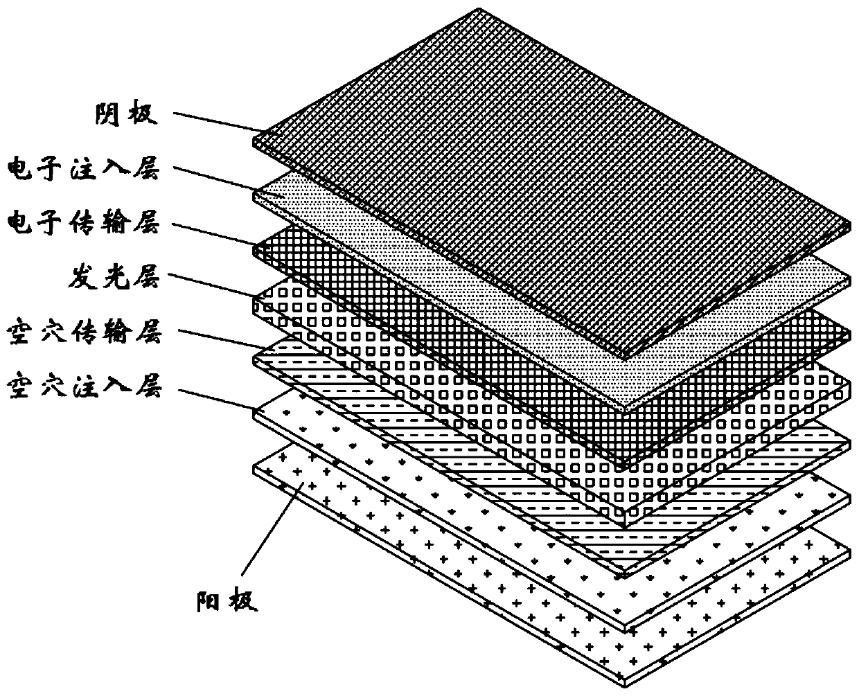
[0109] The substrate is then placed in a vacuum chamber. The standard pressure is set at 1×10⁻⁶ Torr. Thereafter, on the ITO substrate with CuPc NPB RH-001+(btp)2Ir(acac)((5%) Alq3 LiF and Al The sequence forms layers of organic matter.

[0110] At 0.9mA, the brightness is equal to 1227d / m2 (6.0V). At this time, CIEx=0.659, y=0.329.

no. 2 approach

[0112] The ITO glass substrate was patterned to have a light emitting area of ​​3 mm x 3 mm. Then, the patterned ITO glass substrate was washed.

[0113] The substrate is then placed in a vacuum chamber. The standard pressure is set at 1×10⁻⁶ Torr. Thereafter, on the ITO substrate with CuPc NPB RH-007+(btp)2Ir(acac)(5%) Alq3 LiF and Al The sequence forms layers of organic matter.

[0114] At 0.9mA, the brightness is equal to 1098cd / m2 (6.3V). At this time, CIEx=0.659y=0.330.

no. 3 approach

[0116] The ITO glass substrate was patterned to have a light emitting area of ​​3 mm x 3 mm. Then, the patterned ITO glass substrate was washed.

[0117] The substrate is then placed in a vacuum chamber. The standard pressure is set at 1×10⁻⁶ Torr. Thereafter, on the ITO substrate with CuPc NPB RH-073+(btp)2Ir(acac)(5%) Alq3 LiF and Al The sequence forms layers of organic matter.

[0118] At 0.9mA, the brightness is equal to 1232cd / m2 (6.1V). At this time, CIEx=0.659, y=0.329.


PUM


Abstract

The invention discloses a phosphorescent compound and an organic luminescent device employing the same. The phosphorescent compound comprises a structural formula 1 shown in the description and a structural formula 2 shown in the description, wherein in the structural formula 1 and the structural formula 2, Z is independently selected from the following structures: formulae shown in the description; X1 or X2 is independently selected from a N atom or C atom; either X1 or X2 is N; and Ar is independently selected from C6-C30 aryl and C2-C30 heteroaryl. According to the phosphorescent compound and the organic luminescent device employing the same, the visibility is lowered along with improvement of color purity, even, the device also expeditiously operates at low voltage when the color purity is high, the current efficiency is increased, and the luminescence efficiency is high in case of high internal quantum efficiency; and meanwhile, the phosphorescent compound is employed as a luminescent material of an organic light emitting diode device, the manufacturing process is simple, the process efficiency is high, and the production cost is low.

Description


Claims


Application Information

Patent Timeline
Owner YURUI SHANGHAI CHEM
Why Eureka
Try Eureka