Steel rail production process with limited participation of universal mill

A universal rolling mill and production process technology, applied in the direction of rolling mill control devices, metal rolling stands, metal rolling mill stands, etc., can solve problems such as dimensional fluctuations in the height direction of the rail head, and solve the problems of dimensional fluctuations and high and low points, and improve The effect of rail finished pass rate and high-speed rail running smoothness

Active Publication Date: 2020-05-08
HANDAN IRON & STEEL GROUP +1
View PDF6 Cites 2 Cited by
  • Summary
  • Abstract
  • Description
  • Claims
  • Application Information

AI Technical Summary

Benefits of technology

This technology allows for precise control over how much material goes into rails during production without any changes or variations from previous designs that could affect their quality level negatively impacting its performance.

Problems solved by technology

This patented technical solution describes how current methods of producing rails involve rolling steel plugs with an intermediate barrel during final processing. These processes result in excessive amounts of scrap materials that can negatively impact driving safety issues if they go wrongly after being sent offline.

Method used


Image

  • Steel rail production process with limited participation of universal mill
  • Steel rail production process with limited participation of universal mill
  • Steel rail production process with limited participation of universal mill

Examples


Embodiment 1~7

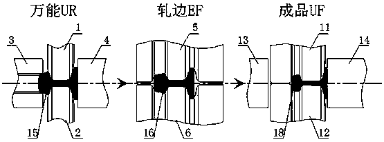
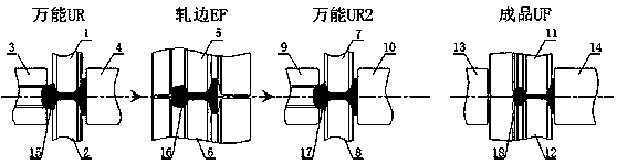
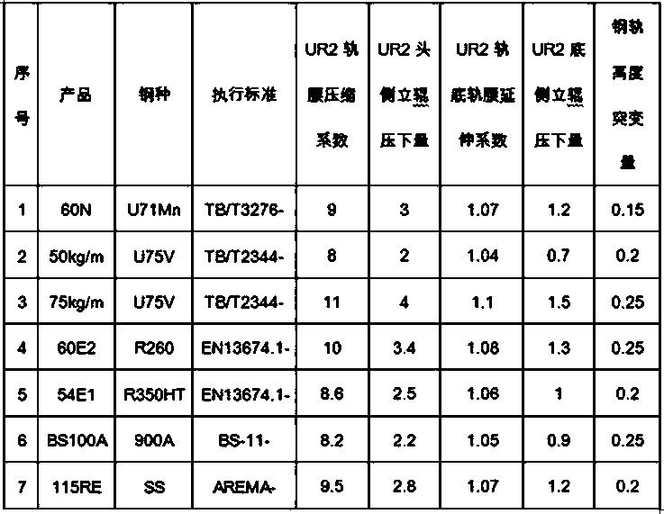
[0036] In TB / T3276-iron standard 60N rail, TB / T2344-iron standard 50kg / m and 75kg / m rail, EN13674.1-European standard 60E2 and 54E1 rail, BS-11-British standard BS100A rail, SS American standard 115RE rail In the process design and production, the rail production process with limited participation of the universal rolling mill was adopted. The last rolling process of the universal rolling mill is universal UR-edge rolling EF-universal UR2 rolling and forming a continuous rolling relationship. Universal UR and edge rolling EF adopt conventional design, universal UR2 adopts light reduction, limited participation rolling design scheme, universal UR2 The pass design parameters are shown in Table 1:


PUM


Abstract

The invention relates to a steel rail production process with limited participation of a universal mill and belongs to the technical field of steel rail rolling in metallurgical industry. The steel rail production process comprises the following steps of forming a universal UR2 hole pattern between a product UF hole pattern and an edge rolling EF hole pattern; carrying out tandem rolling on a rolled piece among universal UR, edge rolling EF and universal UR2; arranging product UF independently; and carrying out head-tripping rolling. By adopting a production scheme of limited participation ofrolling under soft reduction when the hole pattern of UR2 is designed, the steel rail rolled piece subjected to product UF is controlled precisely in a rail head height direction, so that the dimensional fluctuation of a steel rail product in the height direction is solved effectively and the operating smoothness of a high speed rail is improved.

Description


Claims


Application Information

Patent Timeline
Owner HANDAN IRON & STEEL GROUP
Why Eureka
Try Eureka