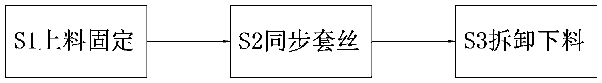
Cast molding finishing process for pipe fitting threaded unions
A technology of casting forming and joints, which is applied to manufacturing tools, metal processing equipment, tangent devices, etc., can solve the problems of low work efficiency, high cost, heavy quality of threading machines, etc., to save adjustment, improve processing efficiency, and simplify The effect of the threading step
- Summary
- Abstract
- Description
- Claims
- Application Information
AI Technical Summary
Problems solved by technology
Method used
Image

Examples
Embodiment Construction
[0030] The embodiments of the present invention will be described in detail below with reference to the accompanying drawings, but the present invention can be implemented in many different ways defined and covered by the claims.
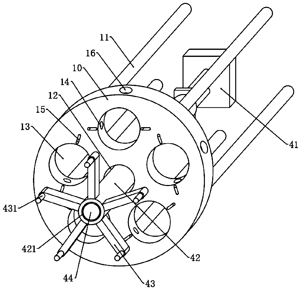
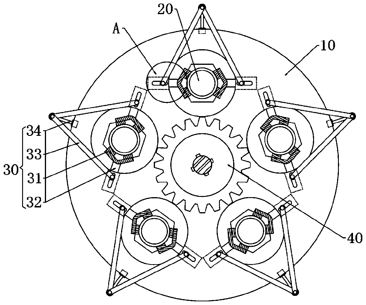
[0031] Such as Figure 1 to Figure 8 As shown, a casting and finishing process of threaded joints of pipe fittings, the casting and finishing process of threaded joints of pipe fittings adopts the following processing machinery, which includes a workbench 10 and a leg 11 arranged at the bottom of the workbench 10. The top of the table 10 is provided with a central hole 12 and a plurality of groups of circular holes 13, the central hole 12 is located at the center of the workbench 10, and the plurality of groups of circular holes 13 are evenly distributed in a circular shape around the central hole 12, and the central hole 12 is provided with sleeves In the device 40, a threaded union 20 is provided in the circular hole 13, and a communication hole 14 i
PUM
 Abstract
Description
Claims
Application Information
 - R&D Engineer
- R&D Manager
- IP Professional
- Industry Leading Data Capabilities
- Powerful AI technology
- Patent DNA Extraction
Browse by: Latest US Patents, China's latest patents, Technical Efficacy Thesaurus, Application Domain, Technology Topic.
© 2024 PatSnap. All rights reserved.Legal|Privacy policy|Modern Slavery Act Transparency Statement|Sitemap