Rapid speed stabilization method for three-phase brushless direct current motor

A brushed DC motor and motor speed technology, applied in the direction of single motor speed/torque control, electronic commutator, starting device, etc., can solve the problems of sacrificing real-time performance, difficulty in achieving expected goals, and complex algorithms, etc., to achieve Reduce the effect of speed overshoot oscillation

Active Publication Date: 2020-09-08
SUZHOU R&D CENT OF NO 214 RES INST OF CHINA NORTH IND GRP
View PDF6 Cites 0 Cited by
  • Summary
  • Abstract
  • Description
  • Claims
  • Application Information

AI Technical Summary

Problems solved by technology

With the progress of society and the development of science and technology, the requirements for the control performance of brushless DC motors are getting higher and higher. In the control of brushless DC motors, the most common method is the PI control method. Although the traditional PI control method can basically meet the control

Method used


Image

  • Rapid speed stabilization method for three-phase brushless direct current motor
  • Rapid speed stabilization method for three-phase brushless direct current motor
  • Rapid speed stabilization method for three-phase brushless direct current motor

Examples


Embodiment 1

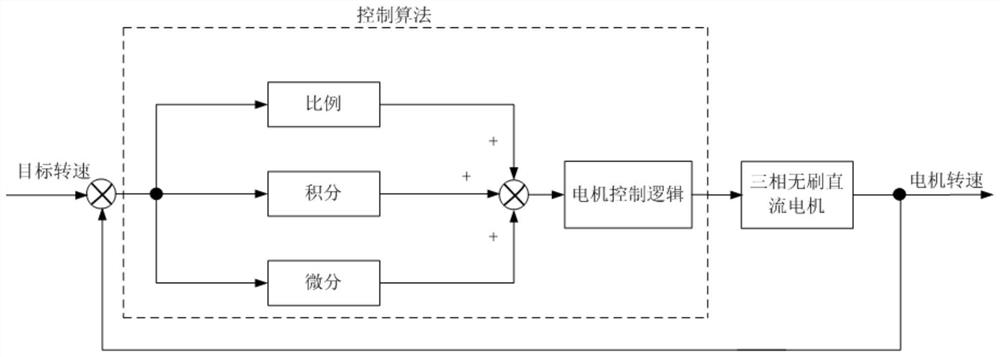
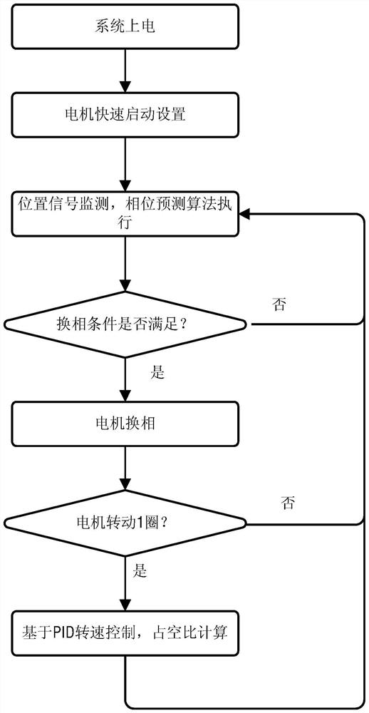
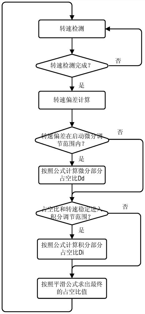
[0083] The content stated in the content of the above invention is only an explanation of the method for fast adjustment of the brushless DC motor. In order to understand the present invention more intuitively, the implementation examples with better effects are described in detail as follows.

[0084] The selected controller is C8051F580 single-chip microcomputer as the control chip realized by the algorithm of this example. The clock is 48MHz, and the PWM duty cycle output is completed through the PAC module, and the duty cycle resolution is 1 / 2048.

[0085] 1. Motor speed detection

[0086] The position signal of the motor is detected by the Hall sensor, and the controller records the detection clock pulse count n used for the same position signal of the motor to appear once, and the rotational speed is represented by the pulse count n. In the traditional motor speed measurement process, it is necessary to follow the formula: speed = 60×CLK / (P×n), where CLK is the samplin


PUM


Abstract

The invention discloses a rapid speed stabilization method for a three-phase brushless direct current motor. The method comprises the steps of 1, detecting the rotating speed of the motor; 2, calculating a difference value between the target rotating speed and the actually measured rotating speed; 3, calculating a duty ratio Dp influenced by the proportionality coefficient Kp; 4, calculating a duty ratio Dd influenced by the differential coefficient Kd; 5, when a set condition is met, calculating a duty ratio DI influenced by the integral coefficient Ki; and 6, according to the rotating speeddifference value, calculating a final duty ratio D by using the coefficients k1 and k2 as duty ratio smoothing processing. The rapid speed stabilization method is applied to a direct-current brushlessmotor control system, the motor adjusting requirements for high speed, high precision and fast response can be met, and meanwhile, the problems of rotating speed overshoot oscillation and the like caused by load changes of the motor are reduced.

Description


Claims


Application Information

Patent Timeline
Owner SUZHOU R&D CENT OF NO 214 RES INST OF CHINA NORTH IND GRP
Why Eureka
Try Eureka