Semiconductor structure and manufacturing method thereof

A semiconductor and via hole technology, applied in the field of semiconductor structures and their manufacturing, can solve the problems of reducing product yield, affecting the electrical connection performance between the redistribution layer and the embedded chip structure, and difficulty in laser energy control, achieving electrical Effects of sexual connection

Pending Publication Date: 2021-06-22
ADVANCED SEMICON ENG INC
View PDF0 Cites 0 Cited by
  • Summary
  • Abstract
  • Description
  • Claims
  • Application Information

AI Technical Summary

Benefits of technology

This patented technology allows for precise placement of electric connections within electronic devices without damaging them or causing damage during fabrication processes. It involves forming these connections directly onto the device's surface instead of adding extra components like wires or connectors.

Problems solved by technology

This patented technology describes how current methods for embedding chips into materials have limitations when created with certain types of structures that require precise control over their placement during processing or use. These difficulties are caused by variations in lasers' ability to penetrate different layers on top of each other without causing issues like misalignment.

Method used


Image

  • Semiconductor structure and manufacturing method thereof
  • Semiconductor structure and manufacturing method thereof
  • Semiconductor structure and manufacturing method thereof

Examples


Embodiment Construction

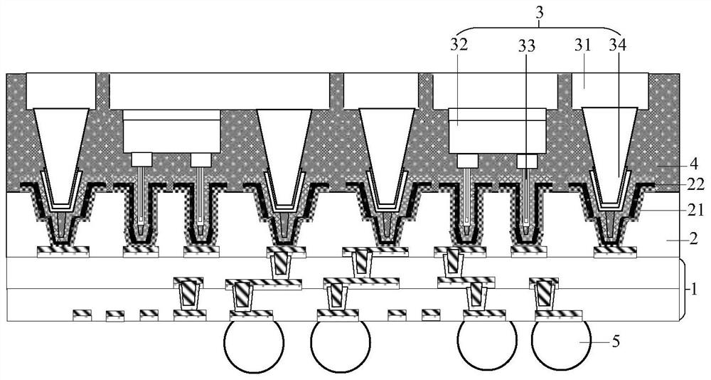
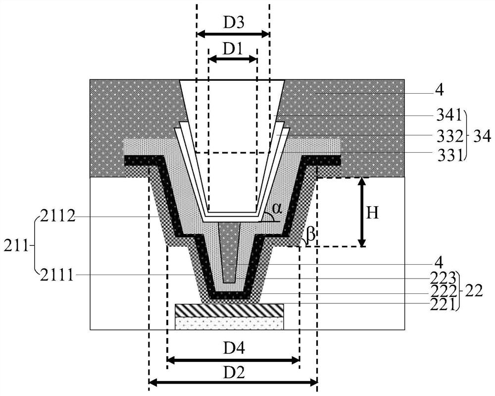
[0035] The specific implementation manners of the present disclosure will be described below in conjunction with the accompanying drawings and examples. Those skilled in the art can easily understand the technical problems solved by the present disclosure and the technical effects produced through the contents recorded in this specification. It should be understood that the specific embodiments described here are only used to explain related inventions, rather than to limit the invention. In addition, for the convenience of description, only the parts related to the related invention are shown in the drawings.

[0036] It should be noted that the structures, proportions, sizes, etc. shown in the accompanying drawings of the specification are only used to match the content recorded in the specification for the understanding and reading of those skilled in the art, and are not intended to limit the implementation of the present disclosure. There are limited conditions, so it has no


PUM


Abstract

The invention discloses a semiconductor structure and a manufacturing method thereof. The method comprises the following steps: forming an electric connecting piece on a circuit substrate, defining a preset position of a via hole on a printing layer on a rewiring layer in a transfer printing manner, reconfiguring an electric connecting layer on the preset position, and jointing the circuit substrate comprising the electric connecting piece with the rewiring layer comprising the electric connecting layer, wherein the electric connection layer is electrically connected with the electric connection piece through reflow soldering. The electrical connection between the rewiring layer and the circuit substrate is realized by accurately defining the electrical contact between the rewiring layer and the circuit substrate.

Description


Claims


Application Information

Patent Timeline
Owner ADVANCED SEMICON ENG INC
Why Eureka
Try Eureka