Enhanced heat dissipation control method of electric vehicle

A control method and technology for electric vehicles, applied to electrochemical generators, circuits, electrical components, etc., can solve the problems of reducing the volume of the battery box, the inability to guarantee temperature uniformity and reliability, and reducing the distance between batteries, so as to improve the The effect of cooling efficiency, improving safety and stability, and reducing structural complexity

Pending Publication Date: 2021-11-02
YANGZHOU UNIV
View PDF5 Cites 0 Cited by
  • Summary
  • Abstract
  • Description
  • Claims
  • Application Information

AI Technical Summary

Benefits of technology

This technology improves how well it cools down batteries by making them more efficient at conductive materials like metal plates or wires that are used for connecting components together. It also makes sure they work safely during use without any problems caused from overheated parts.

Problems solved by technology

This patented technical problem addressed in this patents relates to improving the performance and lifespan of an electrochemically rechargeable (referred to herein after also referred to as secondary) lithium ion cell used in electrical cars due to its higher capacity compared to existing cells. To address these challenges, various methods have been proposed such as direct immersion into liquids or incorporation within solid materials like ceramics. However, current systems are either too complex or require more space because they use fluid instead of solvents, making it difficult to achieve optimal results without sacrificing their effectiveness over longer periods of time.

Method used


Image

  • Enhanced heat dissipation control method of electric vehicle
  • Enhanced heat dissipation control method of electric vehicle
  • Enhanced heat dissipation control method of electric vehicle

Examples


Embodiment 1

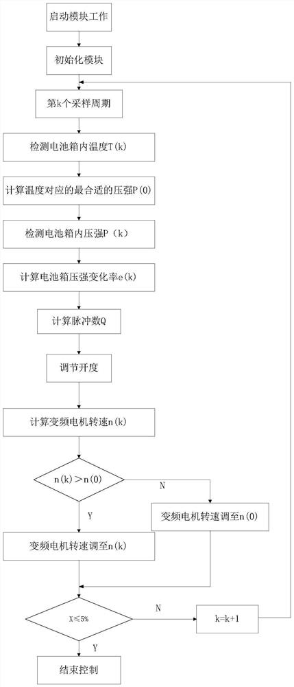
[0035] refer to figure 1 , which is the first embodiment of the present invention, this embodiment provides a method for strengthening heat dissipation control of an electric vehicle, including:

[0036] S1: Detect the real-time temperature T and pressure P inside the battery box through the battery box temperature and pressure detection module 100 .

[0037] The temperature and pressure detection module 100 of the battery box in this embodiment is a temperature sensor and a pressure sensor. The temperature sensor is installed in the middle of the reinforced heat dissipation plate in the battery box, and the pressure sensor is installed at the air inlet of the battery box cover. Communication; when the temperature sensor and pressure sensor collect temperature T and pressure P, the temperature sensor and pressure sensor signals are collected through the analog input module of PLC, and the temperature T(k) and pressure P(k) are obtained through analog-to-digital conversion ).

Embodiment 2

[0061] In order to verify and explain the technical effect adopted in this method, this embodiment compares the energy consumption before and after frequency conversion, and compares the test results by means of scientific demonstration, so as to verify the real effect of this method.

[0062] In the pumping of the battery box, in order to obtain the maximum suction volume and a certain degree of vacuum, the motor of the vacuum pump is always at the maximum speed. When the vacuum degree in the battery box is low, long-term full-load operation will generate a lot of useless work. Cause waste of electric energy; in the step-by-step control of this method, if it is detected that the vacuum is low, first reduce the opening of the electric control valve, and then reduce the speed of the vacuum pump to reduce the suction volume at this time, so as to maintain the vacuum in the battery box. In a certain range of vacuum degree, the control module 400 can effectively save electric energy b


PUM


Abstract

The invention discloses an enhanced heat dissipation control method of an electric vehicle. The method is characterized by comprising the following steps: detecting the real-time temperature T and pressure P in a battery box through a battery box temperature and pressure detection module; calculating the pressure P (0) of the optimal heat dissipation efficiency corresponding to the temperature T according to the real-time temperature T in the battery box; calculating the change rate of the pressure in the battery box through the pressure P, and adjusting the opening degree of the electric adjusting valve through the electric adjusting control valve module according to the change rate; and if the opening degree of the electric control valve is adjusted to 100%, controlling and adjusting the rotating speed of a vacuum pump motor through a vacuum pump frequency conversion adjustment control module, and ending the control till that the pressure error rate X is less than or equal to 5%. The heat dissipation efficiency of the battery module can be improved, the structural complexity of the battery module is reduced, the operation safety and stability of the battery module are improved, and the application of gas-liquid two-phase boiling heat transfer in an electric vehicle is promoted.

Description


Claims


Application Information

Patent Timeline
Owner YANGZHOU UNIV
Why Eureka
Try Eureka