Hemp fiber crusher

A technology of crusher and hemp fiber, which is applied in the direction of grain processing, etc., can solve the problems of maintaining high-quality cutting and the difficulty of high-efficiency and meeting the requirements of hemp fiber cutting treatment, so as to optimize the cavity structure layout, make it difficult to collect, and reduce difficult cutting effect

Inactive Publication Date: 2021-11-30
临沂市永全气体有限公司
View PDF0 Cites 0 Cited by
  • Summary
  • Abstract
  • Description
  • Claims
  • Application Information

AI Technical Summary

Benefits of technology

This patented technology describes an improved design for a small machine tool called Micrafibre (MF). It uses two types of tools: one works with the smaller parts being worked on, like paper or rubbing them together; another works well but only at certain points where there's no material getting mixed up between itself. By optimizing these designs, Mf will work better without requiring extra equipment compared to traditional methods.

Problems solved by technology

The technical problem addressed by this patented technology relates to improving efficiency during producing gas cylinds with improved durability without relying on harmful chemicals or other methods like sizing agents.

Method used


Image

  • Hemp fiber crusher
  • Hemp fiber crusher
  • Hemp fiber crusher

Examples


Embodiment Construction

[0030] It should be noted that any combination among the following embodiments is possible.

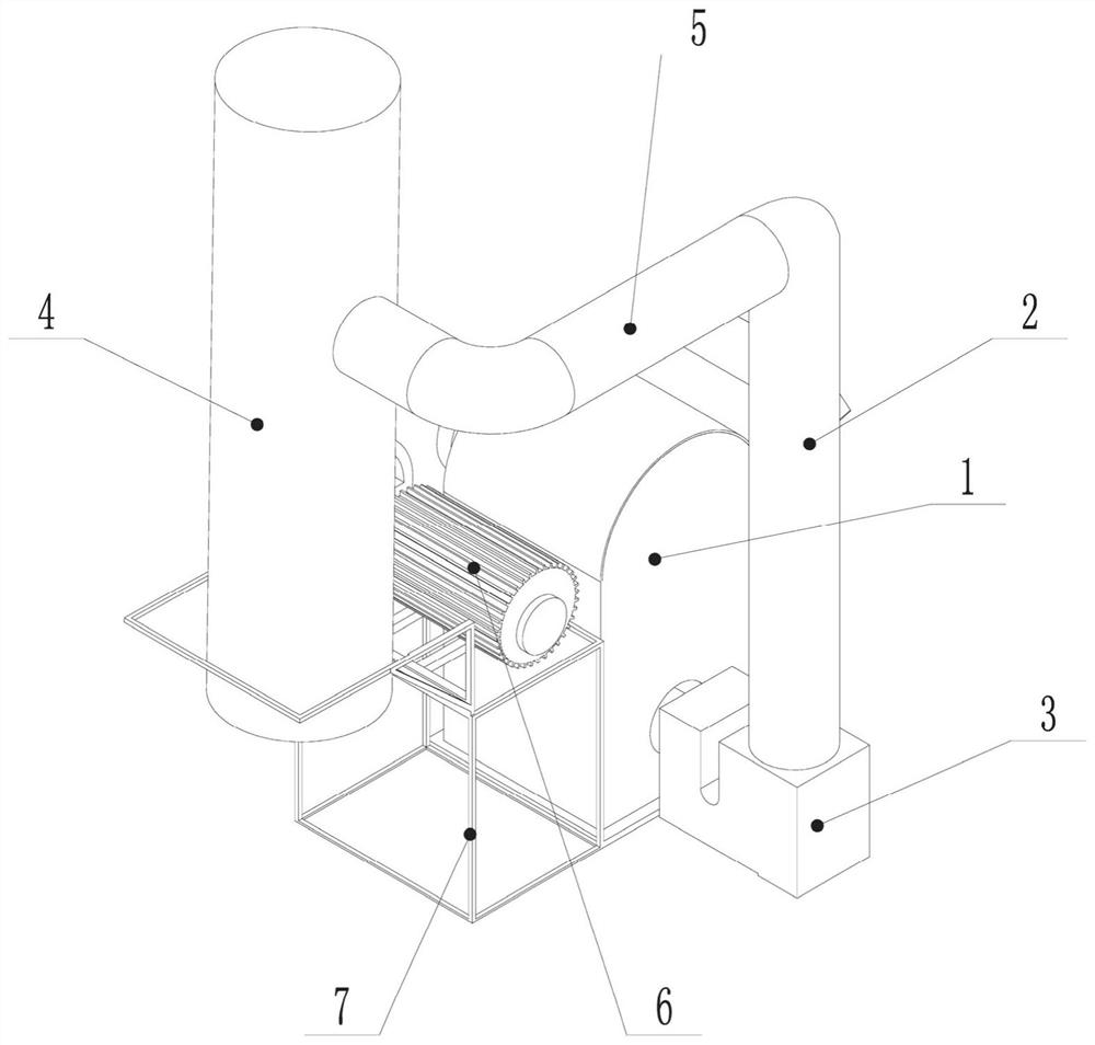
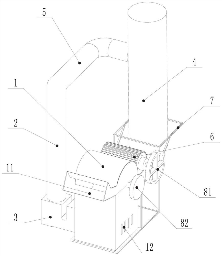
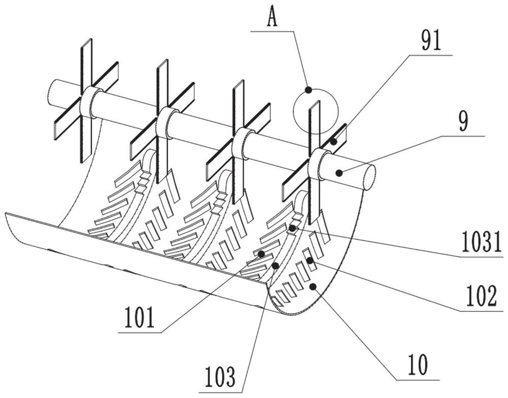
[0031] In a typical implementation of the present invention, this embodiment discloses a hemp fiber crusher. The hemp fiber crusher in this embodiment is used to crush the hemp fiber until the length of the hemp fiber is 6-7mm. The hemp fiber that is the short bunch shape enters in a container through suction; body and the second cavity, a partition drain plate 10 is provided between the first cavity and the second cavity, and the shell 1 is provided with an inlet 11 and an outlet, the inlet 11 is connected to the first cavity, the outlet is connected to the second cavity, and the second cavity is connected to the second cavity. A rotating shaft 9 is arranged in a cavity, and the rotating shaft 9 is connected to a plurality of blades 91, and the rotating shaft 9 is also connected to a power source; the second cavity is also connected to a suction mechanism; the edges on both sides of the


PUM


Abstract

The invention discloses a hemp fiber crusher, which belongs to the technical field of plant fiber treatment. According to the hemp fiber crusher, a rotor cutting knife designed according to the physical characteristics of hemp fibers is adopted, the cavity structure arrangement of a whole device is optimized, and the crusher can still meet the required specification while operating efficiently. The hemp fiber crusher comprises blades, a rotating shaft, a shell and a suction mechanism, a first cavity and a second cavity are formed in the shell, a partition leakage plate is arranged between the first cavity and the second cavity, the rotating shaft is arranged in the first cavity, is connected with the multiple blades and is further connected with a power source, the second cavity is further connected to the suction mechanism, and the edges of the two sides of each blade are sawtooth-shaped.

Description


Claims


Application Information

Patent Timeline
Owner 临沂市永全气体有限公司
Why Eureka
Try Eureka