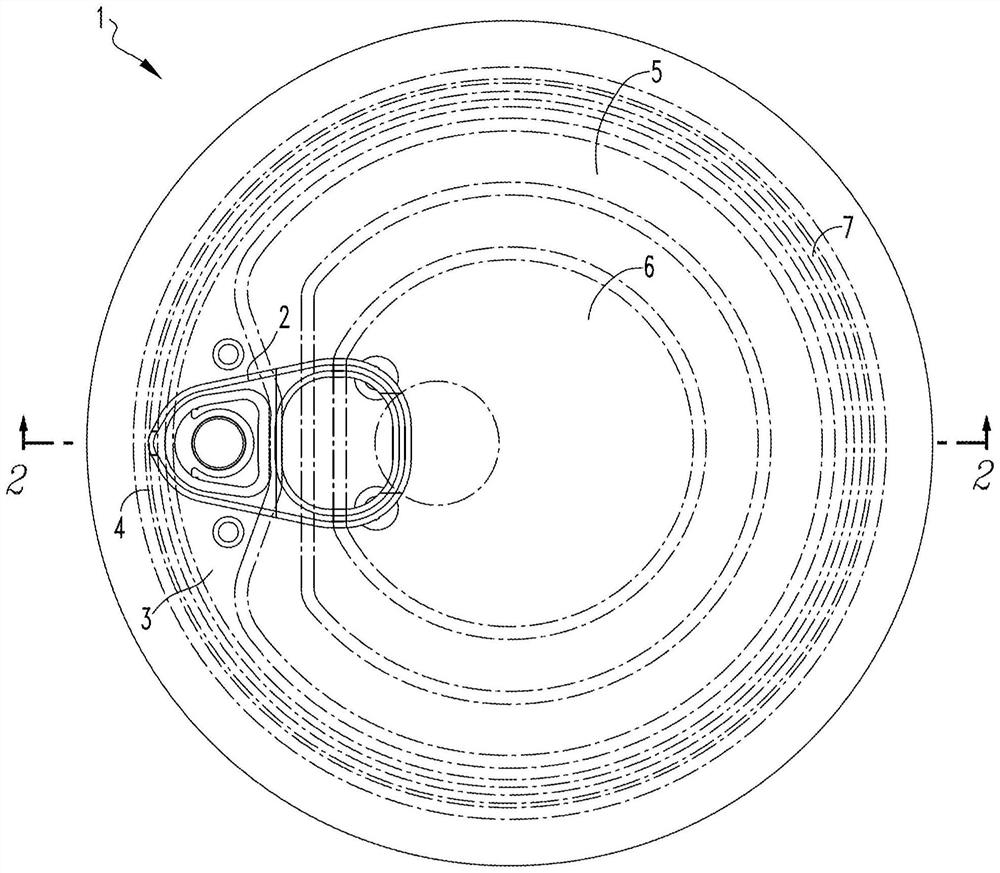
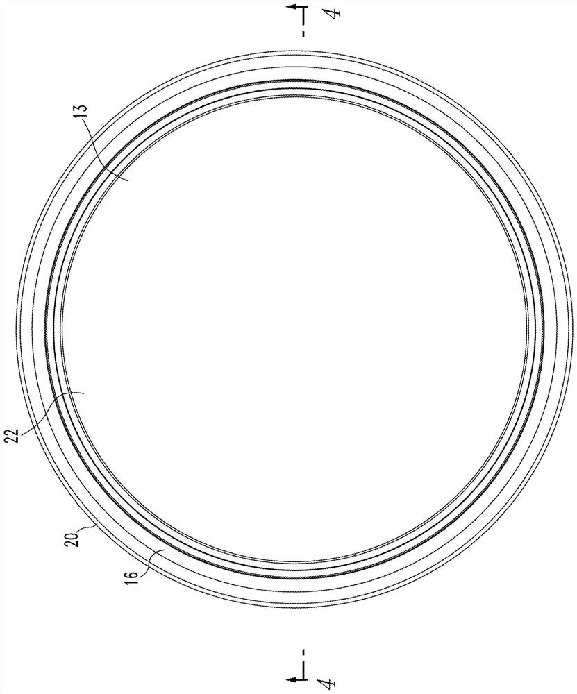
Reverse pressure can end
A can end, annular part technology, applied in the field of tools for providing such can ends, can solve problems such as influence
- Summary
- Abstract
- Description
- Claims
- Application Information
AI Technical Summary
Problems solved by technology
Method used
Image
Examples
Embodiment Construction
[0036]It should be understood that certain elements illustrated in the drawings herein and described in the following specification are exemplary embodiments of the disclosed concepts only, provided as non-limiting examples for purposes of illustration only. Thus, specific dimensions, orientations, components, number of parts used, embodiment configurations and other physical characteristics related to the embodiments disclosed herein are not to be considered as limiting the scope of the disclosed concepts.
[0037] Directional phrases such as clockwise, counterclockwise, left, right, top, bottom, up, down, and their derivatives, as used herein, relate to the orientation of elements shown in the drawings unless expressly stated otherwise herein. It does not limit the claims.
[0038] As used herein, the singular forms "a", "an" and "the" include plural references unless the context clearly dictates otherwise.
[0039] As used herein, "configured [verb]" means that the identified
PUM
 Abstract
Description
Claims
Application Information
 - R&D Engineer
- R&D Manager
- IP Professional
- Industry Leading Data Capabilities
- Powerful AI technology
- Patent DNA Extraction
Browse by: Latest US Patents, China's latest patents, Technical Efficacy Thesaurus, Application Domain, Technology Topic.
© 2024 PatSnap. All rights reserved.Legal|Privacy policy|Modern Slavery Act Transparency Statement|Sitemap


