Machining unit multi-tool-magazine linkage configuration method

A configuration method and processing unit technology, applied in metal processing equipment, metal processing machinery parts, manufacturing tools, etc., can solve the problems of unreasonable allocation of cutting tools, complex structure of parts, high processing cost, etc., to reduce inventory waste, reduce etc. Time, the effect of increasing resilience

Active Publication Date: 2022-04-12
NANJING UNIV OF AERONAUTICS & ASTRONAUTICS +1
View PDF10 Cites 0 Cited by
  • Summary
  • Abstract
  • Description
  • Claims
  • Application Information

AI Technical Summary

Benefits of technology

The invention describes an improved method for planning and preparation of cutting tools used during manufacturing processes. It involves displaying realistic images or measurements from the process while calculating how much material needs being removed based upon factors like workpiece size, type of metal needed, etc., which helps make sure they are working properly before rebuilding them again when necessary. This approach improves productivity and reduces costs associated therewith. Additionally, this technology allows users to easily customize their own cutting tools through software programming techniques. Overall, these technical improvements enhance the accuracy, speediness, usability, and overall effectiveness of industrial mills' (IMM) systems.

Problems solved by technology

The technical problem addressed by this patented technology relates to efficiently producing various items quickly without excessive use of resources like labor and materials during peak periods when there are few spare tools needed at once. This results from the limitation on how many tools may be used per machine due to limitations associated with current methodologies.

Method used


Image

  • Machining unit multi-tool-magazine linkage configuration method
  • Machining unit multi-tool-magazine linkage configuration method
  • Machining unit multi-tool-magazine linkage configuration method

Examples


Embodiment Construction

[0028] Embodiments of the present invention will be further described in detail below in conjunction with the accompanying drawings.

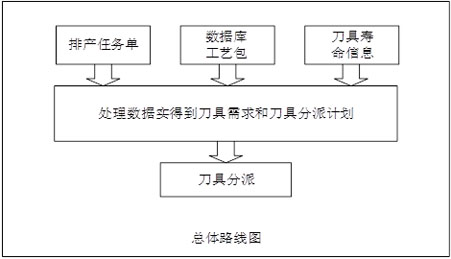
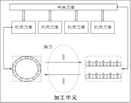
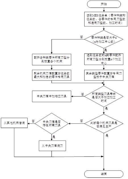
[0029] Such as figure 2 As shown, a hydraulic servo parts intelligent processing unit includes a central tool magazine and four CNC machine tool magazines. The feature of this processing unit is that each machine tool is processing the current workpiece process, and at the same time, it realizes the release and delivery of the borrowed tool required for the next process to be processed in the input buffer zone. Therefore, based on this, preparing the tool before processing starts, and transporting it to the corresponding tool position by the manipulator according to the handle number can reduce the number of tool adjustments in subsequent production, which is of great help to improve production efficiency. First, the production order is obtained based on intelligent scheduling. When a batch of production order is received in the production of th


PUM


Abstract

The invention discloses a multi-tool-magazine linkage configuration method for a machining unit. The method comprises the following steps that firstly, the number of special tool types, the number of universal tool types and machining time of all parts are determined; 2, after the types and the number of the machining tools are determined, the machining parts are distributed to all machine tools, and special tools and universal tools corresponding to the machining parts are arranged in machine tool magazines in a matched mode, 3, whether the service life of all the tools of the unit machining center meets the corresponding total machining time or not is judged, and if not, corresponding tools are added to a central tool magazine; and 4, judging whether the tools in the tool magazine of the machine tool meet machining requirements or not before part machining every time, if yes, normal machining is carried out, and if not, the corresponding tools are adjusted from other tool magazines till the production requirements are met. According to the method, the cutter is visualized and digitized, the cutter demand calculation is more accurate, and the cutter can be rapidly and reasonably prepared.

Description


Claims


Application Information

Patent Timeline
Owner NANJING UNIV OF AERONAUTICS & ASTRONAUTICS
Why Eureka
Try Eureka