Spaceborne antenna deployment control system

A technology of spaceborne antenna and control system, which can be applied to antennas, rotating antennas, folding antennas, etc., and can solve the problems of poor reliability and low driving accuracy.

Pending Publication Date: 2022-05-03
SPACETY CO LTD (CHANGSHA)
View PDF4 Cites 0 Cited by
  • Summary
  • Abstract
  • Description
  • Claims
  • Application Information

AI Technical Summary

Problems solved by technology

[0007] Aiming at the problems of low driving precision and poor reliability of the currently used antenna deployment mechanism, this application proposes a spaceborne antenna deployment control system

Method used


Image

  • Spaceborne antenna deployment control system
  • Spaceborne antenna deployment control system
  • Spaceborne antenna deployment control system

Examples


Embodiment 1

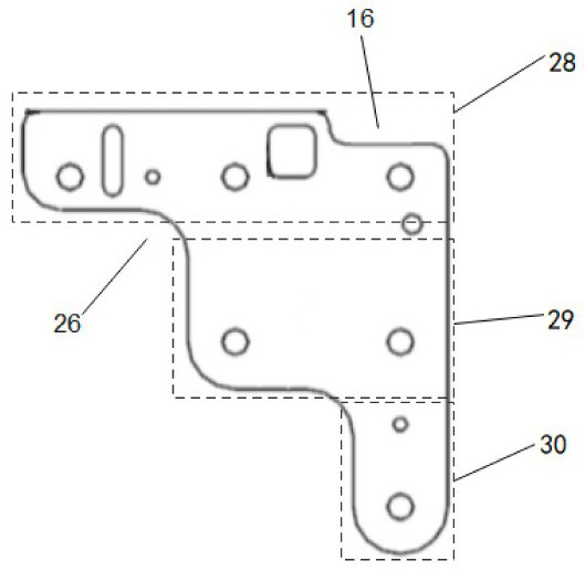
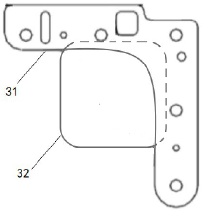
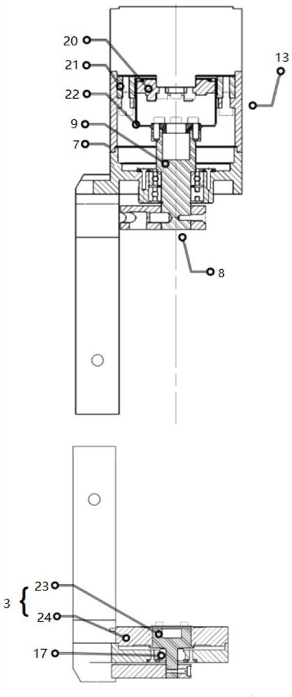
[0027] The present application proposes a spaceborne antenna deployment control system, which is installed between two adjacent planar components 1 , so that the two planar components 1 connected via a drive assembly can rotate relative to each other. In actual use, the two planar members 1 connected by the driving assembly can realize controllable deployment, retraction or adjustment.

[0028] as attached figure 1 ~ attached Figure 4 As shown, the spaceborne antenna deployment control system at least includes a mechanical power output system 2 , a rotation angle measurement component 3 , a first output component 4 and a second output component 5 . This application mainly uses the first output part 4 and the second output part 5 to respectively assemble the mechanical power output system 2 and the rotation angle measurement part 3 to both sides of the planar member 1. The mechanical power output system 2 can be better than ordinary motors. The planar member 1 is driven to unfo


PUM


Abstract

The invention relates to a spaceborne antenna unfolding control system, which at least comprises a mechanical power output system, a rotation angle measuring component, a first output component and a second output component, and takes the extension direction of a virtual rotation axis of two plane components rotating relative to each other as a first direction, the mechanical power output system is provided with a first bearing surface and a second bearing surface, and the two end surfaces of the mechanical power output system are connected to different plane components through first output components correspondingly. The included angle formed between the two plane components can be increased or decreased according to the mode that the relative position relation between the first bearing face and the second bearing face is changed. The rotation angle measuring part is connected to different planar members through the second output part, and the rotation angle measuring part and the mechanical power output system are connected in the mode that the rotation angle measuring part and the mechanical power output system are located on the two sides of the planar members in the first direction respectively and can conduct information interaction with each other.

Description


Claims


Application Information

Patent Timeline
Owner SPACETY CO LTD (CHANGSHA)
Why Eureka
Try Eureka