Visual inertia calibration method and device

A calibration method and inertial technology, applied in the field of vision, can solve problems such as poor calibration accuracy, and achieve the effect of improving the anti-shake effect

Pending Publication Date: 2022-05-13
VIVO MOBILE COMM CO LTD
View PDF0 Cites 0 Cited by
  • Summary
  • Abstract
  • Description
  • Claims
  • Application Information

AI Technical Summary

Problems solved by technology

[0005] The purpose of the embodiment of the present application is to provide a visual-inertial calibration method and its devi

Method used


Image

  • Visual inertia calibration method and device
  • Visual inertia calibration method and device
  • Visual inertia calibration method and device

Examples


Embodiment Construction

[0024] The following will clearly describe the technical solutions in the embodiments of the present application with reference to the drawings in the embodiments of the present application. Obviously, the described embodiments are part of the embodiments of the present application, but not all of them. All other embodiments obtained by persons of ordinary skill in the art based on the embodiments in this application belong to the protection scope of this application.

[0025] The terms "first", "second" and the like in the specification and claims of the present application are used to distinguish similar objects, and are not used to describe a specific sequence or sequence. It should be understood that the terms so used are interchangeable under appropriate circumstances such that the embodiments of the application can be practiced in sequences other than those illustrated or described herein, and that references to "first," "second," etc. distinguish Objects are generally of o


PUM


Abstract

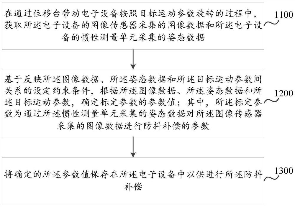
The invention discloses a visual inertia calibration method and device, and belongs to the technical field of vision. The method comprises the following steps: acquiring image data acquired by an image sensor of the electronic equipment and attitude data acquired by an inertial measurement unit of the electronic equipment in a process of driving the electronic equipment to rotate according to target motion parameters through a displacement table; determining a parameter value of a calibration parameter according to the image data, the attitude data and the target motion parameter based on a set constraint condition reflecting a relationship among the image data, the attitude data and the target motion parameter; wherein the calibration parameters are parameters for performing anti-shake compensation on image data acquired by the image sensor through attitude data acquired by the inertial measurement unit; and storing the determined parameter value in the electronic equipment for carrying out the anti-shake compensation.

Description


Claims


Application Information

Patent Timeline
Owner VIVO MOBILE COMM CO LTD
Why Eureka
Try Eureka