Apparatus for depositing a low work function material

a technology of low work function and apparatus, which is applied in the direction of vacuum evaporation coating, electric heating, coating, etc., can solve the problem that the activation procedure cannot be used for micro-meter-scale protrusions, and achieve the effect of low work function materials

Inactive Publication Date: 2006-10-10
LAWRENCE LIVERMORE NAT SECURITY LLC
View PDF9 Cites 4 Cited by
  • Summary
  • Abstract
  • Description
  • Claims
  • Application Information

AI Technical Summary

Benefits of technology

The technical effect of this patented invention is that it provides a way to make surfaces with lower work functions than previously possible.

Problems solved by technology

This patent describes a method and device for creating low work function surfaces on a substrate with specific compositions. These methods involve laser ablation techniques where small particles called atoms or molecules are removed from the substrate's surface through evaporation. By controlling this removal, the resulting structure may include field emitters or other devices.

Method used


Image

  • Apparatus for depositing a low work function material
  • Apparatus for depositing a low work function material

Examples


Embodiment Construction

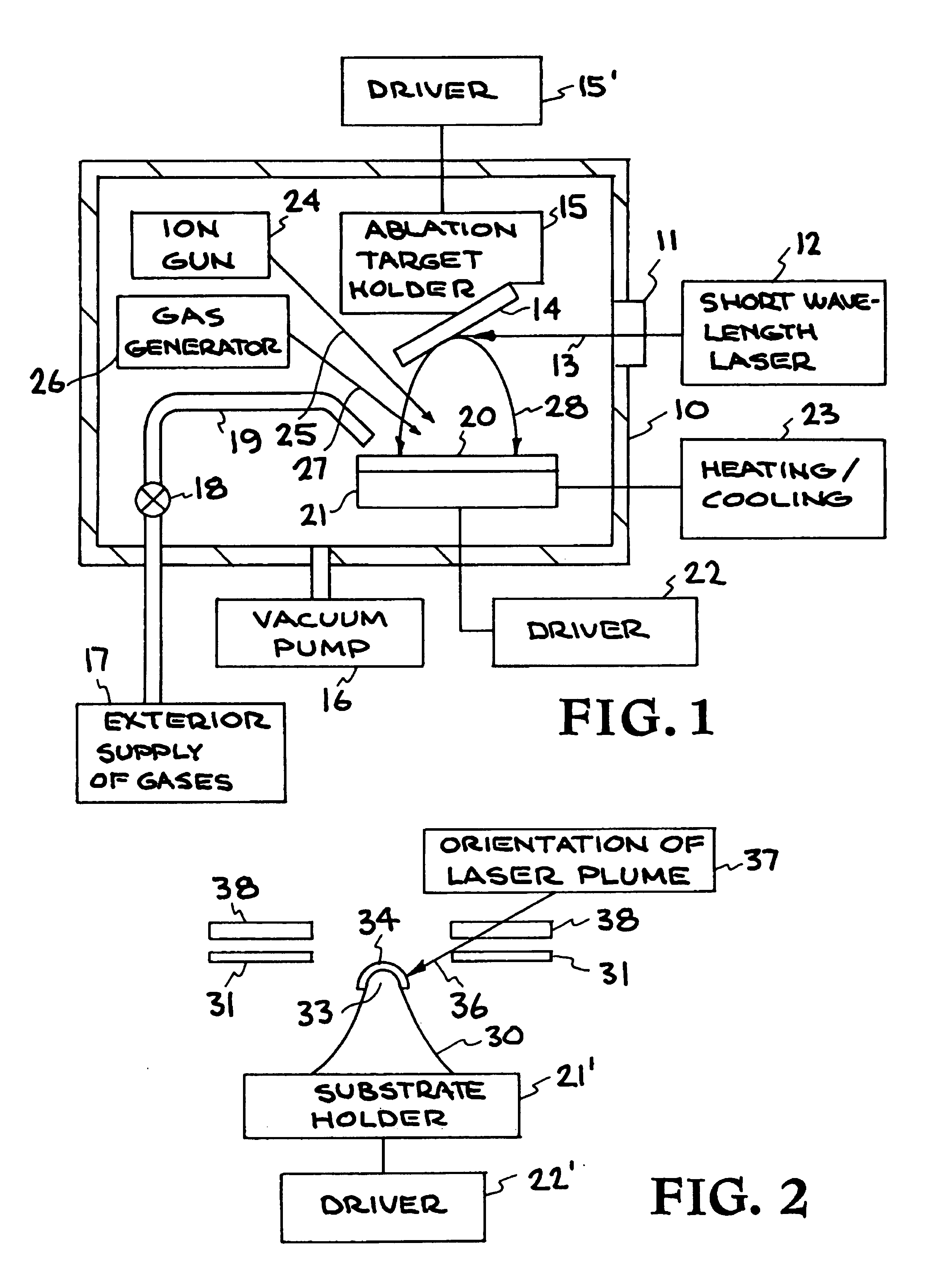
[0018]The present invention is directed to depositing low work function material on a surface by laser ablation using short-wavelength photons. The short-wavelength photons are at or below visible wavelength and thus are in the range of 200 to 550 nm. The elemental composition of the deposited low work function layer can be controlled by the composition of the laser ablated target and the gaseous environment in which the ablation process is performed. The invention is particularly applicable for use in fabricating devices using electron emission from sharp tips, such as in tunneling microscopy and flat panel display technology, wherein it is important that the tips: (1) have low work functions, (2) are smooth on a nanometer scale, and (3) are stable in varying gaseous environments and under high electric field conditions. Tests have established that each of these three (3) properties has been achieved by the process and apparatus of the present invention. Since laser ablation can be pe


PUM

PropertyMeasurementUnit
Timeaaaaaaaaaa
Angleaaaaaaaaaa
Wavelengthaaaaaaaaaa

Abstract

Short-wavelength photons are used to ablate material from a low work function target onto a suitable substrate. The short-wavelength photons are at or below visible wavelength. The elemental composition of the deposit is controlled by the composition of the target and the gaseous environment in which the ablation process is performed. The process is carried out in a deposition chamber to which a short-wavelength laser is mounted and which includes a substrate holder which can be rotated, tilted, heated, or cooled. The target material is mounted onto a holder that spins the target during laser ablation. In addition, the deposition chamber is provided with a vacuum pump, an external gas supply with atomizer and radical generator, a gas generator for producing a flow of molecules on the substrate, and a substrate cleaning device, such as an ion gun. The substrate can be rotated and tilted, for example, whereby only the tip of an emitter can be coated with a low work function material.

Description


Claims


Application Information

Patent Timeline
Owner LAWRENCE LIVERMORE NAT SECURITY LLC
Why Eureka
Try Eureka