Automatic chemical material mixing stirrer
A mixer and mixing mechanism technology, applied in mixers, mixer accessories, mixers with rotating mixing devices, etc., can solve problems such as uneven mixing by hand, difficulty in controlling the proportion of various materials, and difficulty in maintaining accuracy.
- Summary
- Abstract
- Description
- Claims
- Application Information
AI Technical Summary
Problems solved by technology
Method used
Image

Examples
Embodiment 1
[0024] A chemical material automatic mixing mixer, such as figure 1 As shown, it includes a bottom plate 1, a workbench 2, a motor 3, a stirring mechanism 4, a uniform discharge mechanism 5, and a receiving box 9. The top of the bottom plate 1 is connected with a workbench 2, and the top of the workbench 2 is provided with a blanking port. The motor 3 is connected to the right side of the table 2, the stirring mechanism 4 is connected between the output shaft of the motor 3 and the top of the workbench 2, the uniform discharge mechanism 5 is connected between the stirring mechanism 4 and the top of the workbench 2, and the left side of the top of the bottom plate 1 A material receiving box 9 is placed, and the material receiving box 9 is slidably matched with the base plate 1.
[0025] When the staff needs to mix materials, they can first place the receiving box 9 under the discharge port of the workbench 2, then put the materials to be stirred in the uniform discharge mechanism
Embodiment 2
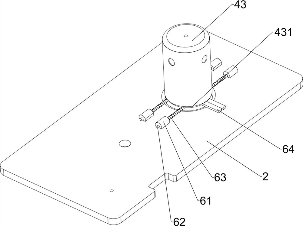
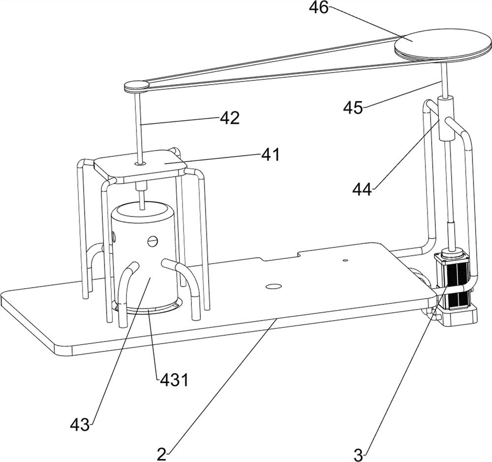
[0027] On the basis of Example 1, such as figure 2 with image 3 As shown, the stirring mechanism 4 includes a fixed plate 41, a first rotating shaft 42, a stirring sheet 421, a stirring drum 43, a material retaining plate 431, a first column sleeve 44, a second rotating shaft 45 and a first transmission device 46, and the working The left side of the top of the table 2 is connected with a fixed plate 41, and the center of the fixed plate 41 is rotatably connected with a first rotating shaft 42. The bottom of the first rotating shaft 42 is provided with a stirring piece 421, and the top of the workbench 2 is connected with a stirring cylinder 43. The bottom of the barrel 43 is symmetrically equipped with a baffle plate 431, which is detachable. The material baffle plate 431 is located above the discharge port, the material stirring piece 421 is located in the material mixing cylinder 43, and the right side of the workbench 2 is connected with a first The column sleeve 44, the t
Embodiment 3
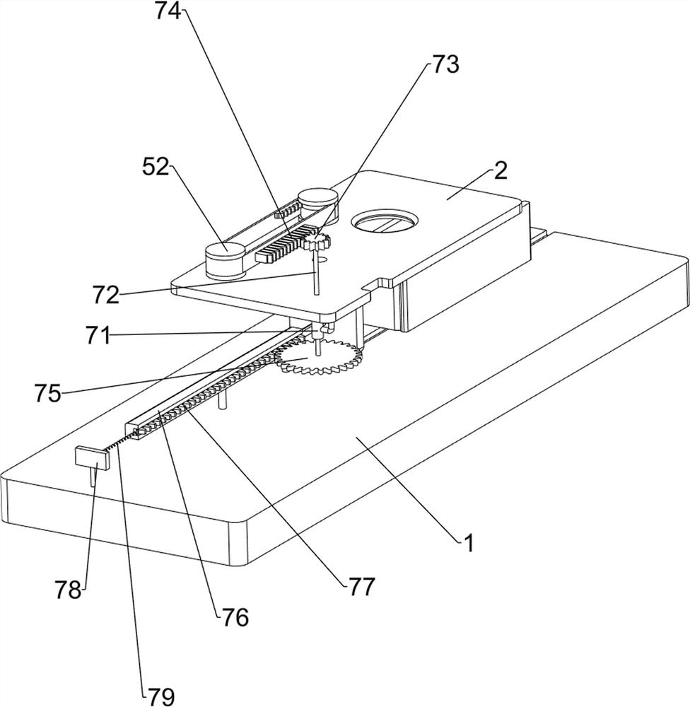
[0030] On the basis of Example 2, such as Figure 4 with Figure 5 As shown, the uniform discharge mechanism 5 includes a third rotating shaft 51, a second transmission device 52, a second column sleeve 53, a fourth rotating shaft 54, a first spur gear 55, a second spur gear 56, a fixed ring 57, a large gear 58. The third column sleeve 581, the fifth rotating shaft 582, the retaining gear 59, the material storage barrel 510 and the discharge pipe 511, the top right side of the workbench 2 is provided with a third rotating shaft 51, and the top of the third rotating shaft 51 is connected to the motor 3 output shafts are connected with a second transmission device 52, and the right side of the top of the workbench 2 is connected with a second column sleeve 53, and the second column sleeve 53 is provided with a fourth rotating shaft 54 for rotation, and the bottom of the fourth rotating shaft 54 is provided with The first spur gear 55, the first spur gear 55 is in transmission
PUM
 Abstract
Description
Claims
Application Information
 - R&D Engineer
- R&D Manager
- IP Professional
- Industry Leading Data Capabilities
- Powerful AI technology
- Patent DNA Extraction
Browse by: Latest US Patents, China's latest patents, Technical Efficacy Thesaurus, Application Domain, Technology Topic.
© 2024 PatSnap. All rights reserved.Legal|Privacy policy|Modern Slavery Act Transparency Statement|Sitemap