Automatic production equipment for power module

A power module and production equipment technology, applied in the field of power module automatic production equipment, to achieve the effects of improving uniformity and consistency, conveniently fixing positioning nails, and reducing the probability of damage

Pending Publication Date: 2021-09-03
河南省丽晶美能电子技术有限公司
View PDF7 Cites 0 Cited by
  • Summary
  • Abstract
  • Description
  • Claims
  • Application Information

AI Technical Summary

Problems solved by technology

[0003] The purpose of the present invention is to solve the problems existing in the existing power module production line, and to provide an automatic power module product

Method used


Image

  • Automatic production equipment for power module
  • Automatic production equipment for power module
  • Automatic production equipment for power module

Examples


Embodiment Construction

[0038] The following will clearly and completely describe the technical solutions in the embodiments of the present invention with reference to the accompanying drawings in the embodiments of the present invention. Obviously, the described embodiments are only some, not all, embodiments of the present invention.

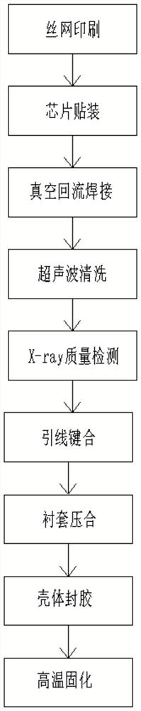
[0039] Such as Figure 1-14 As shown, an automatic production equipment for power modules, including a screen printing machine, an automatic placement machine, a vacuum reflow welding machine, an ultrasonic cleaning machine, an X-ray testing machine, an automatic wire bonding machine, and a laser marking machine connected in sequence , bushing pressing machine, shell filling machine, and high-temperature curing machine; among them, the screen printing machine uses the solder paste setting graphics to print on the surface of the DBC copper plate, making preliminary preparations for the subsequent automatic placement, in order to improve the tin For the efficiency of past


PUM


Abstract

The invention discloses automatic production equipment for a power module, and relates to the technical field of semiconductor device manufacturing. The automatic production equipment comprises a screen printer, an automatic chip mounter, a vacuum reflow soldering machine, an ultrasonic cleaning machine, an X-ray detector, an automatic lead bonding machine, a laser marking machine, a bushing pressing machine, a shell filling machine and a high-temperature curing machine which are connected in sequence. The automatic production equipment is characterized in that a printing screen plate and a substrate placing plate are sequentially arranged on the screen printing machine from top to bottom corresponding to the lower part of a printing scraper, and the equipment has the advantages of high production efficiency and high automation degree.

Description


Claims


Application Information

Patent Timeline
Owner 河南省丽晶美能电子技术有限公司
Why Eureka
Try Eureka