Switch cabinet monitoring device and monitoring method thereof

A monitoring device and switchgear technology, applied in measurement devices, radiation pyrometry, supervision desk/panel, etc., can solve the problems of increasing cost, limited measurement range, occupying the internal space of switchgear, etc., to achieve cost saving and convenience View and ensure the effect of safe and reliable operation

Pending Publication Date: 2021-09-24
扬中海潮电力设备有限公司
View PDF1 Cites 2 Cited by
  • Summary
  • Abstract
  • Description
  • Claims
  • Application Information

AI Technical Summary

Problems solved by technology

[0004] Infrared equipment is usually used for monitoring the temperature of the above-mentioned power cabinets. However, since the measurement range of each infrared temperature probe is very limited, if you want to detect the temperature of multiple devices in

Method used


Image

  • Switch cabinet monitoring device and monitoring method thereof
  • Switch cabinet monitoring device and monitoring method thereof
  • Switch cabinet monitoring device and monitoring method thereof

Examples


Embodiment

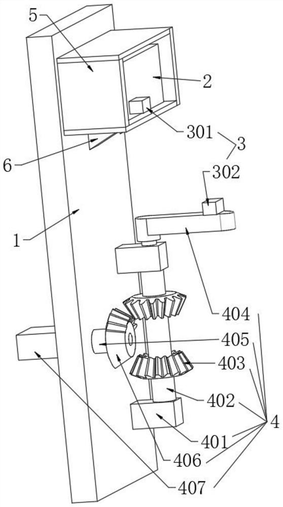
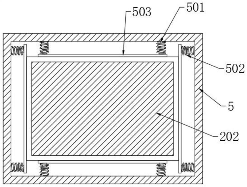
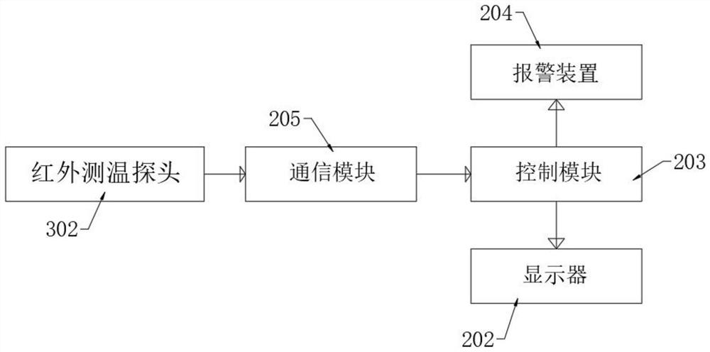
[0030] see Figure 1-3 , the present invention provides the following technical solutions: a switchgear monitoring device, including a switchgear 1, a monitoring device 2 installed on the side plate of the switchgear 1, and a plurality of detection devices 3 located below the monitoring device 2, the monitoring device 2 includes a shell 201, a display 202, a control module 203, an alarm device 204, and a communication module 205. A plurality of detection devices 3 include a humidity sensor 301 installed on the outer wall of the casing 201. The humidity sensor 301 is connected to the control module 203 through wireless communication, and is connected to the control module 203 through wireless communication. The communication module 205 is displayed on the display 202. The display 202 is provided with buttons for adjusting the switch, and infrared temperature measuring probes 302 located at different positions in the switch cabinet 1. The infrared temperature measuring probe 302 is


PUM


Abstract

A switch cabinet monitoring device provided by the present invention comprises a switch cabinet, a monitoring device and a plurality of detection devices, the plurality of detection devices comprise humidity sensors installed on the outer side wall of a shell and infrared temperature measurement probes located at different positions in the switch cabinet, and the infrared temperature measurement probes are fixed through swing pieces. And the infrared temperature measurement probes are connected with the control module through wireless communication. The monitoring method of the switch cabinet monitoring device comprises the steps that S1, a motor is started firstly, and the output end of the motor drives a main shaft to rotate; s2, the infrared temperature measurement probes collect infrared rays emitted by an electrical apparatus element; s3, the acquired data is sent to a communication module, and the data is processed through a mainboard; and s4, the processed data are displayed through a displayer, and an alarm device gives an alarm when the temperature exceeds the early warning range. The motor drives the main shaft to rotate, and the mounting seat drives the infrared temperature measurement probes to rotate, so that the detection area of the infrared temperature measurement probes is increased, and detection blind spots are reduced.

Description


Claims


Application Information

Patent Timeline
Owner 扬中海潮电力设备有限公司
Why Eureka
Try Eureka