Strong current pulse protection circuit and method

A protection circuit and electric pulse technology, applied in the field of strong electric pulse protection circuit and strong electric pulse protection, can solve the problems of increased circuit complexity, poor versatility and high maintenance cost, and achieve the effect of improving robustness

Pending Publication Date: 2022-03-25
武汉船舶通信研究所
View PDF0 Cites 0 Cited by
  • Summary
  • Abstract
  • Description
  • Claims
  • Application Information

AI Technical Summary

Problems solved by technology

[0003] In related technologies, the threshold current of the circuit breaker is generally a fixed value, but different interfaces have different operating currents, w

Method used


Image

  • Strong current pulse protection circuit and method
  • Strong current pulse protection circuit and method
  • Strong current pulse protection circuit and method

Examples


Embodiment Construction

[0023] It should be noted that, in the case of no conflict, the embodiments of the present invention and the features in the embodiments can be combined with each other. The present invention will be described below with reference to the accompanying drawings and examples.

[0024] In order to enable those skilled in the art to better understand the technical solutions of the present invention, the following will clearly and completely describe the technical solutions in the embodiments of the present invention in conjunction with the drawings in the embodiments of the present invention. Obviously, the described implementation Examples are only some of the embodiments of the present invention, but not all of them, and should belong to the protection scope of the present invention.

[0025] It should be noted that the terms "first" and "second" in the description and claims of the present invention and the above drawings are applicable to distinguish similar objects, and are not n


PUM


Abstract

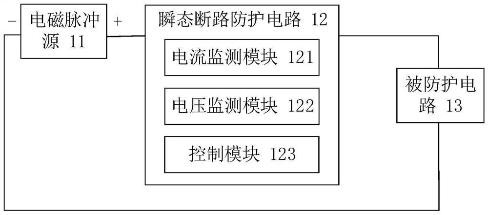
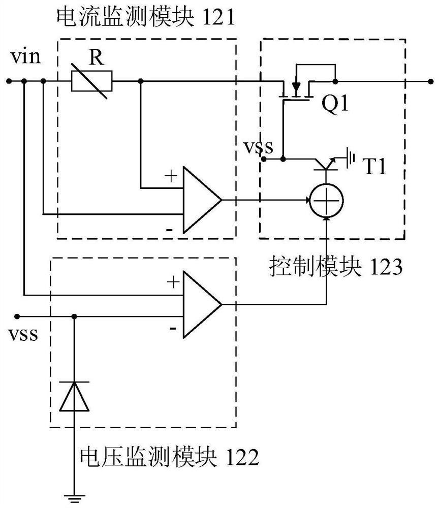
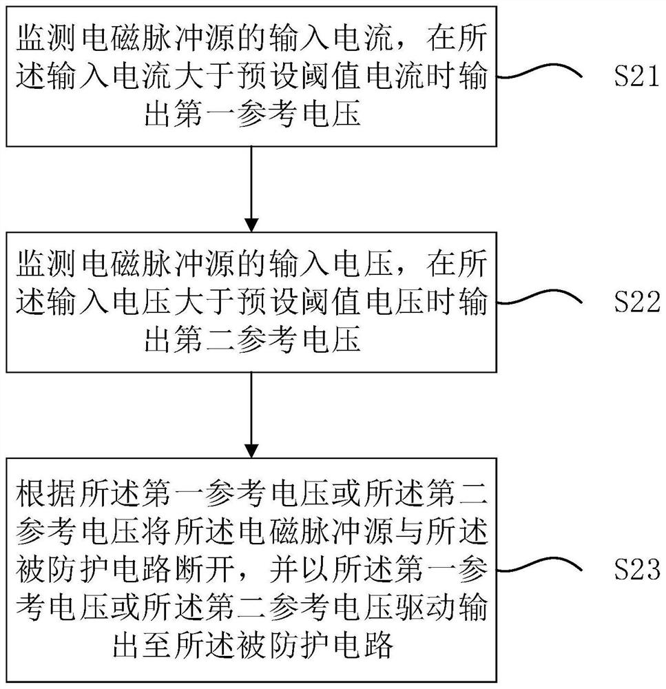
The invention discloses a strong current pulse protection circuit which comprises an electromagnetic pulse source, a transient open circuit and a protected circuit. The input ends and the output ends of the transient circuit break circuit and the protected circuit are respectively connected with the positive electrode and the negative electrode of the electromagnetic pulse source; the transient circuit break circuit comprises a current monitoring module which outputs a first reference voltage to a control module when a current input by an electromagnetic pulse source is greater than a preset threshold current; the voltage monitoring module outputs a second reference voltage to the control module when the voltage input by the electromagnetic pulse source is greater than a preset threshold voltage; and the control module is used for disconnecting the electromagnetic pulse source from the protected circuit when receiving the first reference voltage or the second reference voltage, and driving the protected circuit by the reference voltage. According to the invention, under the strong electromagnetic pulse effect of the electromagnetic pulse source, the current passing through the protected circuit does not exceed the threshold current, the input voltage of the protected circuit does not exceed the threshold voltage, and the performance of each component can still be kept stable.

Description


Claims


Application Information

Patent Timeline
Owner 武汉船舶通信研究所
Why Eureka
Try Eureka