Current limiting circuit and electric equipment with same

A current limiting and circuit technology, applied in the field of electronic information, can solve problems such as high cost, current limiting of power tubes, large error of current limiting circuit, etc.

Pending Publication Date: 2022-05-06
SUZHOU NOVOSENSE MICROELECTRONICS
View PDF5 Cites 0 Cited by
  • Summary
  • Abstract
  • Description
  • Claims
  • Application Information

AI Technical Summary

Problems solved by technology

[0003] One of the purposes of the present invention is to provide a current limiting circuit to solve the technical problems in the prior art that the cu

Method used


Image

  • Current limiting circuit and electric equipment with same
  • Current limiting circuit and electric equipment with same
  • Current limiting circuit and electric equipment with same

Examples


Embodiment Construction

[0018] The present invention will be described in detail below in conjunction with specific embodiments shown in the accompanying drawings. However, these embodiments do not limit the present invention, and any structural, method, or functional changes made by those skilled in the art according to these embodiments are included in the protection scope of the present invention.

[0019] It should be noted that the term "comprising" or any other variation thereof is intended to cover a non-exclusive inclusion such that a process, method, article, or apparatus comprising a set of elements includes not only those elements, but also items not expressly listed other elements, or also include elements inherent in such a process, method, article, or apparatus. In addition, the terms "first", "second", "third", "fourth", etc. are used for descriptive purposes only and should not be construed as indicating or implying relative importance.

[0020] During the working process of electrical


PUM


Abstract

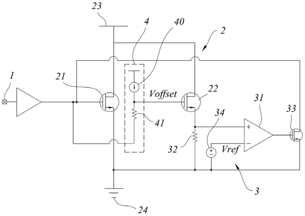
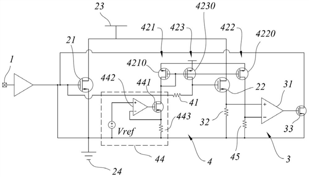
The invention discloses a current limiting circuit and electric equipment with the current limiting circuit, and the current limiting circuit comprises a current input end, a mirror image circuit and an adjusting circuit which are sequentially connected. The mirror image circuit comprises a first field effect transistor and a second field effect transistor of which grids are connected with each other; the input side of the adjusting circuit is connected with the source electrode of the second field-effect transistor and reference voltage, the output side of the adjusting circuit is connected with the grid electrode of the first field-effect transistor, and the adjusting circuit is configured to control the level of the grid electrode of the first field-effect transistor according to the output of the source electrode of the second field-effect transistor and the reference voltage; the current limiting circuit further comprises a compensation circuit, the compensation circuit is connected with the grid electrode of the second field effect transistor and is configured to output compensation voltage, and the value of the compensation voltage is equal to the value of the reference voltage. According to the current limiting circuit provided by the invention, errors in the current limiting process can be controlled, and the technical effects of cost, structure and general applicability of current limiting are achieved.

Description


Claims


Application Information

Patent Timeline
Owner SUZHOU NOVOSENSE MICROELECTRONICS
Why Eureka
Try Eureka